EasyManuals Logo

Cisco Catalyst 4500 Series Installation Guide

Cisco Catalyst 4500 Series
194 pages
To Next Page IconTo Next Page
To Previous Page IconTo Previous Page
Page #123 background imageLoading...
Page #123 background image
4-9
Catalyst 4500 Series Switches Installation Guide
78-14409-08
Chapter 4 Removing and Replacing FRUs
Removing and Replacing the Power Supply
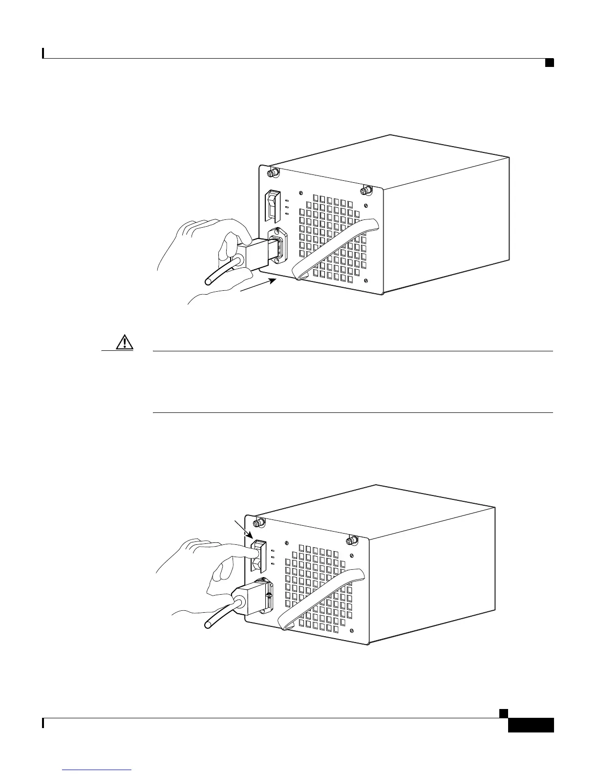
Figure 4-9 Plugging the Power Cord into the Power Supply
Step 10 Connect the other end of the power cord to an AC-power input source.
Caution In a system with multiple power supplies, connect each power supply to a separate
AC power source. In the event of a power source failure, if the second source is
still available, it can maintain maximum overcurrent protection for each power
connection.
Step 11 Press the power switch down to the on (|) position (see Figure 4-10).
Figure 4-10 Powering On the Power Supply
79142
Power switch
79143

Table of Contents

Other manuals for Cisco Catalyst 4500 Series

Questions and Answers:

Question and Answer IconNeed help?

Do you have a question about the Cisco Catalyst 4500 Series and is the answer not in the manual?

Cisco Catalyst 4500 Series Specifications

General IconGeneral
SeriesCatalyst 4500 Series
CategorySwitch
Layer SupportLayer 2, Layer 3
Form FactorModular chassis
StackableNo
Chassis Slots3, 6, 7, 10
Power Supply OptionsAC, DC
RedundancyPower supply, Supervisor engine
Network ManagementCisco IOS Software CLI, SNMP, Cisco Prime Infrastructure
FeaturesSecurity, QoS
Port DensityUp to 384 ports per chassis
Security Features802.1X, ACLs, DHCP Snooping, Dynamic ARP Inspection, IP Source Guard
Supervisor Engine8-E

Related product manuals