5-11
Catalyst 4500 Series Switches Installation Guide
78-14409-08
Chapter 5 Troubleshooting
Troubleshooting Switching Modules
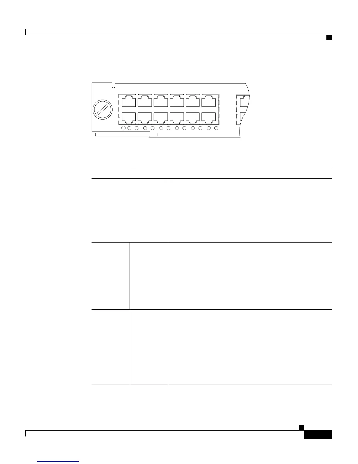
Figure 5-2 10/100BASE-T Port LEDs
17407
STATUS
4
1
2
3
4
5
5
6
6
7
7
8
8
9
9
10
10
11
12
11
12
WS-X4148-RJ
4 PORT
10/100 B
Ta b l e 5-1 Switching Module LEDs
LED Color/State Description
STATUS Indicates the results of a series of self-tests and
diagnostic tests performed by the switch.
Green All the tests pass.
Red A test other than an individual port test failed.
Orange System boot, self-test diagnostics running, or the
module is disabled.
LINK
1
1. Used on the WS-X4232-L3 Ethernet routing module.
Indicates the status of the port.
Green The port is operational (a signal is detected).
Orange The link has been disabled by software.
Flashing
orange
The link has been disabled due to a hardware failure.
Off No signal is detected.
Port
Status
2
2. LEDs labeled 1 through the number of ports on the switching module are the individual port link
LEDs.
Indicates individual port status.
Green The port is operational (a signal is detected).
Orange The link has been disabled by software.
Flashing
orange
The link has been disabled due to a hardware failure.
Off No signal is detected.

 Loading...


