Step 2 Use the appropriate crimping tool to crimp the bare 6-AWG copper ground wire to the supplied grounding
lug.
The grounding lug and hardware used must comply with local and national electrical codes.
Note
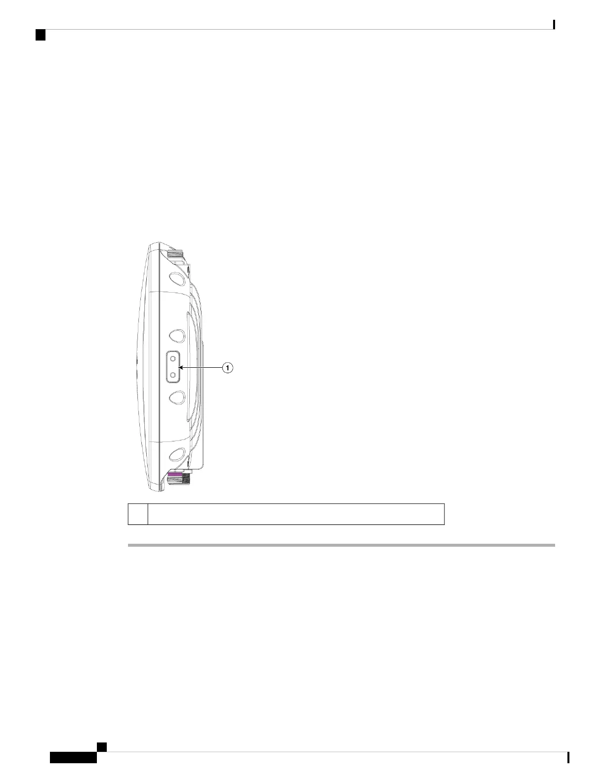
Step 3 Open the anti-corrosion sealant (supplied) and apply a liberal amount over the metal surface called the Ground
Pad, where the ground strap screw holes are located.
Step 4 Connect the grounding lug to the AP grounding screw holes using the supplied two Phillips head screws (M4
x10–mm) with lock washers. Tighten the grounding screw with 22 to 24 lb-in (2.5 to 2.7 Nm) of torque.
Step 5 If necessary, strip the other end of the ground wire and connect it to a reliable earth ground, such as a grounding
rod or an appropriate grounding point on a metal streetlight pole that is grounded.
Figure 12: Position of the Ground Pad on the Right Side of the AP
Ground pad, where the ground strap screw holes are located.1
Powering the Access Point
The AP supports Power-over-Ethernet (PoE) based power sources.
The AP is powered via the PoE input from an inline power injector. Depending on the configuration and
regulatory domain, the required power for full operation is 802.3at.
Cisco Catalyst Wireless 9163E Access Point Hardware Installation and Deployment Guide
28
Installing the Access Point
Powering the Access Point