Thread the screw nut onto the AP threaded port and tighten by hand to be sure the gland seals to the port.
Torque to 15 lbf-in (17 kgf-cm), if possible.
Step 11 Route your Ethernet cable and cut off any excess cable.
Step 12 Install an RJ45 connector on the unterminated cable end and insert it into the power injector or device PoE
port.
Ensure the individual conductor sequence matches the opposite connection end. The typical
sequence follows the T568B pinout standard.
Note
Step 13 Turn on the power to the power injector.
Mounting Antennas
Installing the Omnidirectional Antenna
The CW-ANT-O1-NS-00 is an N-type connector omnidirectional Self-Identifying Antenna (SIA).
Procedure
Step 1 Match the antenna to the corresponding AP port based on the supporting radio band.
For more information, see Supported External Antennas, on page 7.
Step 2 Connect the antennas to the N-connector on the AP.
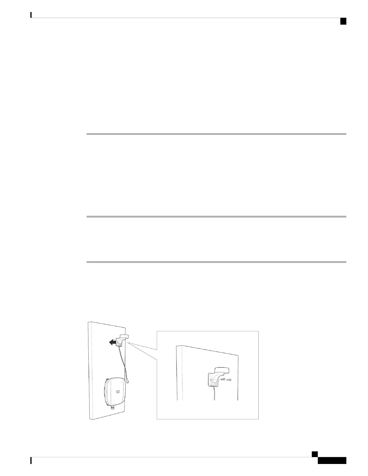
Wall Mounting the GNSS Antenna
The CW-ANT-GPS2-S-00 is a mounting bracket with the GNSS antenna for mounting the antenna to a wall
or a pole.
Figure 16: Wall Mounting a GNSS antenna
Cisco Catalyst Wireless 9163E Access Point Hardware Installation and Deployment Guide
35
Installing the Access Point
Mounting Antennas