The installer is responsible for ensuring that powering the AP from this type of power injector is
allowed by local and/or national safety and telecommunications equipment standards.
Note
Step 4 Ensure that the antennas are connected and that the grounding cable is attached to the AP before you apply
power to the AP.
Step 5 Connect a shielded outdoor-rated Ethernet (CAT5e or better) cable between the power injector and the AP's
PoE-in connector.
Step 6 Connect the Ethernet cable to the AP PoE-In port.
Connecting an Ethernet Cable to the Access Point
Installing a CAT 5e Ethernet Cable and Gland Assembly to the Access Point
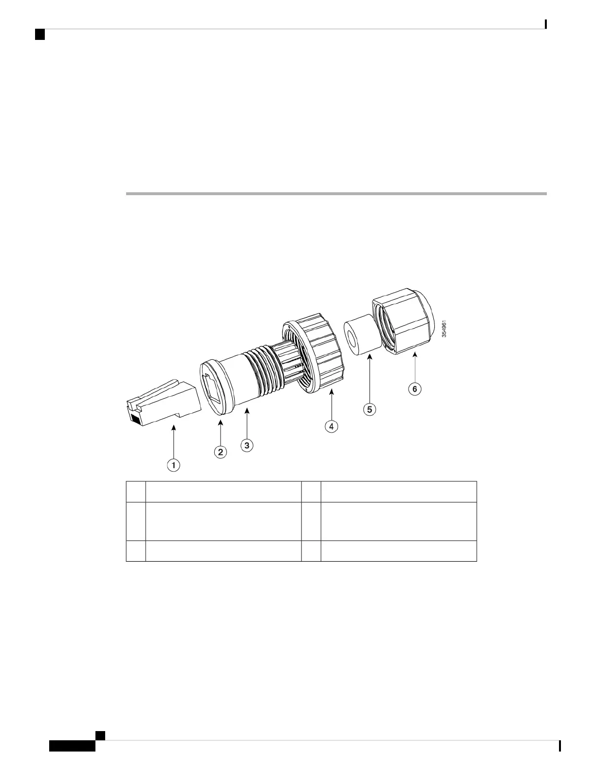
Figure 13: CAT 5e Cable Gland Assembly
Screw nut4CAT 5e RJ45 Plug1
Cable Seal5Gasket
It is pre-attached to the Clamp ring.
2
Cable Sealing Nut6Clamp ring3
Before you begin
You must supply these tools and materials:
• Shielded outdoor-rated CAT 5e Ethernet cable with a diameter of 0.14 to 0.26 inch (3.5 to 6.5mm)
• CAT 5e RJ45 connector and installation tool
• Adjustable wrench or 18–mm box wrench
• CAT 5e gland kit is supplied standard with AP
Cisco Catalyst Wireless 9163E Access Point Hardware Installation and Deployment Guide
30
Installing the Access Point
Connecting an Ethernet Cable to the Access Point