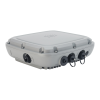
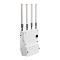
• The provided CAT 5e gland must be used with CAT 5e cable only. When
using CAT 6/6A cable you need to use AIR-ACC-CAT6= kit which is an
orderable accessory from Cisco.
• We recommend the application of dielectric grease on the RJ45 connector
pins as an additional layer of protection from moisture. The dielectric grease
creates a moisture barrier preventing the RJ45 connector pins from corrosion
if the gland's weathertight seal fails.
Note
Procedure
Step 1 Disconnect power to the power injector and ensure all power sources to the AP are turned off.
This unit might have more than one power supply connection. All connections must be
removed to de-energize the unit. Statement 1028
Danger
Step 2 Ensure a 6 AWG ground wire is connected to the AP (see Grounding the Access Point, on page 27).
Step 3 Remove the covering cap from the PoE port.
Step 4 Loosen and remove the cable sealing nut of the cable gland by turning it counterclockwise.
Verify that the cable gland has a rubber seal and a gasket. Ensure that it is not damaged.
Note
If the cable gland and rubber gasket are not installed correctly, it causes the cable grip to leak.
Caution
Step 5 Reinstall Cable Seal and Sealing Nut.
Step 6 Insert the Ethernet cable's unterminated end through the sealing nut end of the cable gland.
Pass the Ethernet cable through the cable seal and pull several inches of cable through the adapted components.
Step 7 Install an RJ45 connector on the Ethernet cable's unterminated end using your Ethernet cable installation tool.
Cisco Catalyst Wireless 9163E Access Point Hardware Installation and Deployment Guide
31
Installing the Access Point
Installing a CAT 5e Ethernet Cable and Gland Assembly to the Access Point
 Loading...

