Before you begin
Ensure that you have the following materials before beginning to mount the GNSS antenna to a wall:
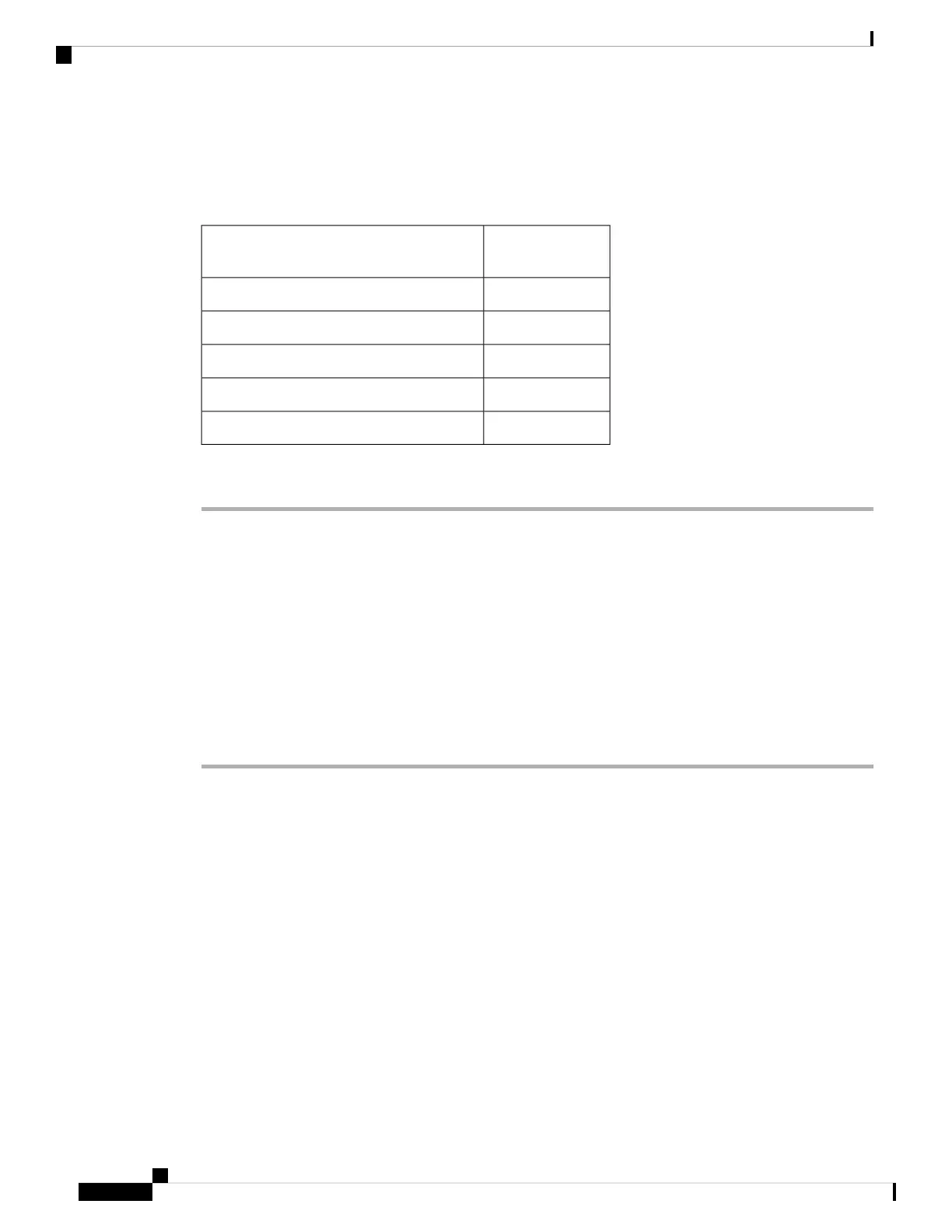
Table 11: Material Required to Mount CW-ANT-GPS2-S-00 to a Wall
Supplied in the
Kit?
Materials Required
YesWall/pole mount bracket
NoTwo wall mounting screws
NoTwo wall anchors (specified for all material)
NoDrill bit for wall anchors
NoElectric drill and standard screwdriver
Procedure
Step 1 Use the GNSS CW-ANT-GPS2-S-00 mounting bracket as a template to mark the two screw hole locations
on the mounting wall.
Step 2 Use two screws and, if required, wall anchors to attach the mounting bracket to the mounting surface. These
screws and anchors are to be sourced independently.
You can use an exterior-grade plywood backboard to mount the GNSS antenna to stucco, cement,
or drywall.
Note
Step 3 Screw an M6 x12–mm screw into each of the two support bolt holes on the bracket.
Step 4 Remove the protective cap and connect the antenna to the GNSS port.
The GNSS port is located at the top of the AP. See Connectors and Ports on the AP, on page 5.
Pole Mounting the GNSS Antenna
The CW-ANT-GPS2-S-00 is a mounting bracket with the GNSS antenna for mounting the antenna to a wall
or a pole.
Cisco Catalyst Wireless 9163E Access Point Hardware Installation and Deployment Guide
36
Installing the Access Point
Pole Mounting the GNSS Antenna