1-4
Installation Guide for Cisco Secure ACS Solution Engine 4.1
OL-9969-03
Chapter 1 Cisco Secure ACS Solution Engine Overview
ACS SE Hardware Description
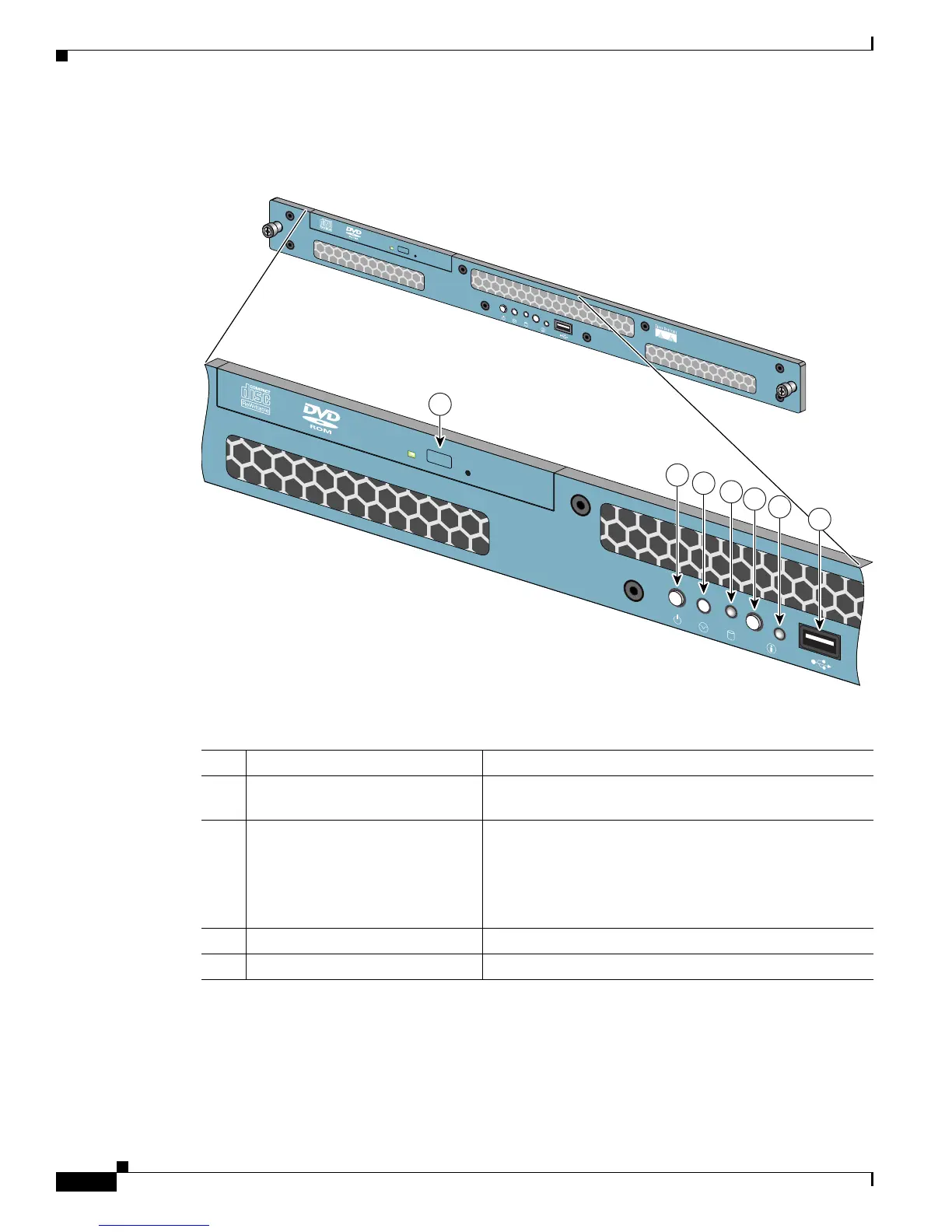
Figure 1-2 Front Panel Switches and Indicators for the Cisco 1113
The following table describes the callouts in Figure 1-2.
149998
1
2
3
4
5
6
CISC
O 1190
BUILDING BR
OADBA
ND SERVICE M
ANAG
ER
7
No. Switch or LED Indicator Description
1 DVD-ROM drive activity LED On = Activity
Off = No Activity
2 Power On/Off button and LED Pushing the power button turns the unit on or off. The LED
in the center of the power On/Off button has three states:
Blinking Green = Power is connected but not on
Green = Power On
Off = Power Off
3 Unused button This button is not operational.
4 HDD LED Indicates that there is activity on the hard drive.