Section 5 — Service and Maintenance
Part No. 750-263 5-3
B. REASSEMBLY
1. Assembly is the reverse of the above instructions.
2. A new rope gasket should be installed on the burner door.
See recommended spare parts list.
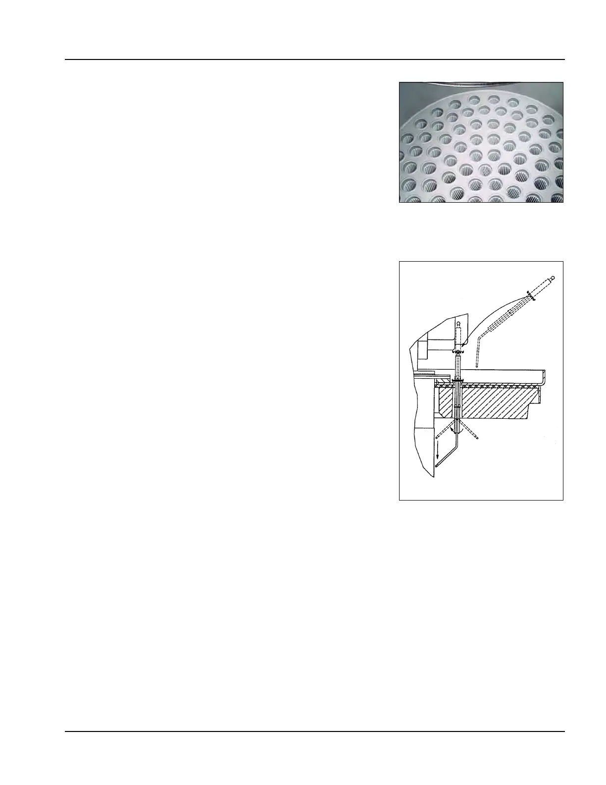
C. IGNITION ELECTRODE AND FLAME ROD
The ignition and ionization electrodes should be replaced annually,
or more frequently if conditions require. Inspect the electrodes
periodically for signs of fouling, displacement, or other damage.
Electrodes should be replaced as shown in Figure 5-4 with the
electrode turned towards the burner mantle after it is inserted into
the burner head. Observe the dimensions below when replacing
(also see Figure 5-5):
3/8” gap between ionization electrode and the surface of the burner
canister.
1/8” gap between ignitor electrode and ground electrode.
7/8” from ignitor electrode to the burner canister.
D. TROUBLESHOOTING
Lockout Conditions
1. Observe lockout code and description - refer to CB Falcon appendix if
necessary.
2. After determining lockout condition, investigate possible causes.
3. When cause is diagnosed, remedy condition.
4. Reset control. Boiler should be able to start normally.
5. If lockout recurs, further investigation is required. Repeat steps 1
through 4 as needed. If necessary, contact your CB service representa-
tive for technical support.
EXAMPLE: Lockout 79 Outlet Temperature High Limit
1. Before resetting control to clear lockout, check for sufficient water flow
through boiler. Possible sources of insufficient flow include closed
water valves, insufficient pump speed, air trapped in boiler (inadequate
air venting), or modulation set point and off point close to outlet high
limit setting.
The CB Falcon system display/interface provides extensive boiler
diagnostic data at the time of lockout that can help in determining
Figure 5-3 Combustion
Chamber and Tube Sheet
Figure 5-4 Electrode Setup