Section 4 — CFC Commissioning
Part No. 750-263 4-17
4. After the ILK input is energized, 10 sec. allowed for IAS input
(combustion air proving) to energize, and purge rate proving fan RPM is
achieved - prepurge time is started.
5. When 30 sec. purge time is complete, the purge fan RPM is changed to
the lightoff speed.
6. As soon as the fan-rpm is equal to the light-off RPM , the Trial for Ignition
(4 sec.) or Pre-Ignition Time is started (depending on configuration).
7. Pre-Ignition Time will energize the ignitor and check for flame.
8. Trial for Ignition.
9. The ignition and the gas valve are switched on.
10.The ignition is turned off at the end of the direct burner ignition period.
11.The fan is kept at the lightoff rate during the stabilization timer, if any.
12.Before the release to modulation, the fan is switched to minimum RPM
for the CH Forced Rate and Slow Start Enable, if the water is colder than
the threshold.
13.Release to modulation.
14.At the end of the CH-heat request the burner is switched off and the fan
stays on until post purge is complete.
15.A new CH-request is blocked for the forced off time set by the Anti Short
Cycle (if enabled).
16.The pump stays on during the pump overrun time (if enabled).
17.At the end of the pump overrun time the pump will be switched off.
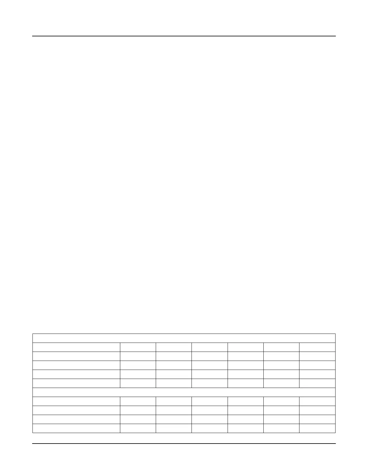
H. FAN SPEED SETTINGS
Because the input is determined by the fan speed, fan speed
settings may have to be modified for the particular application, for
high altitudes, or when using direct vent combustion. Tabl e 4-2
provides the default fan speed settings in typical applications for the
various boiler sizes. To allow safe modulation through the firing
range, these parameters should be initially set to the recommended
speeds. Please contact your authorized Cleaver-Brooks
representative for proper settings in high altitude and direct vent
combustion applications.
Table 4-1 Fan Speed Settings
NATURAL GAS
Setting CFC-500
CFC-750 CFC-1000 CFC-1500 CFC-1800 CFC-2500
Max. Speed (RPM) CH 5500
5300 5300 5300 4600 5000
Max. Speed (RPM) DHW 5500 5300 5300 5300 4600 5000
Min. Speed (RPM) 1300 1200 1100 1200 900 1100
Ignition Fan Speed (Lightoff Rate) 2200 2000 1800 1800 1500 1800
LP GAS/DUAL FUEL
Max. Speed (RPM) CH 5200
5000 5000 5000 4400 4000
Max. Speed (RPM) DHW 5200
5000 5000 5000 4400 4000
Min. Speed (RPM) 1700 1600 1600 1700 1400 1400
Ignition Fan Speed (Lightoff Rate) 2400 2200 2200 2000 1800 2000