Section 4 — CFC Commissioning
Part No. 750-263 4-19
2. Power-Up
1. Ensure blower motor is properly wired for the available power
supply.
2. Verify the voltage (control voltage is 115V-1Ph.-60Hz) to ensure
it is within specifications.
3. Operation Check: Gas Valve, Gas Pressure Switches,
and Combustion Air Proving Switch
Before initial firing of the burner, the gas valve, Low Gas Pressure
Switch (LGPS), High Gas Pressure Switch (HGPS), and Combustion
Air Proving Switch (CAPS) should be checked for proper operation.
• Before proceeding, review Section 4.3 - Control Setpoints for
initial LGPS, HGPS, and CAPS settings.
Note: Close the downstream manual gas shut-off valve before
checking pressure switches and CAPS.
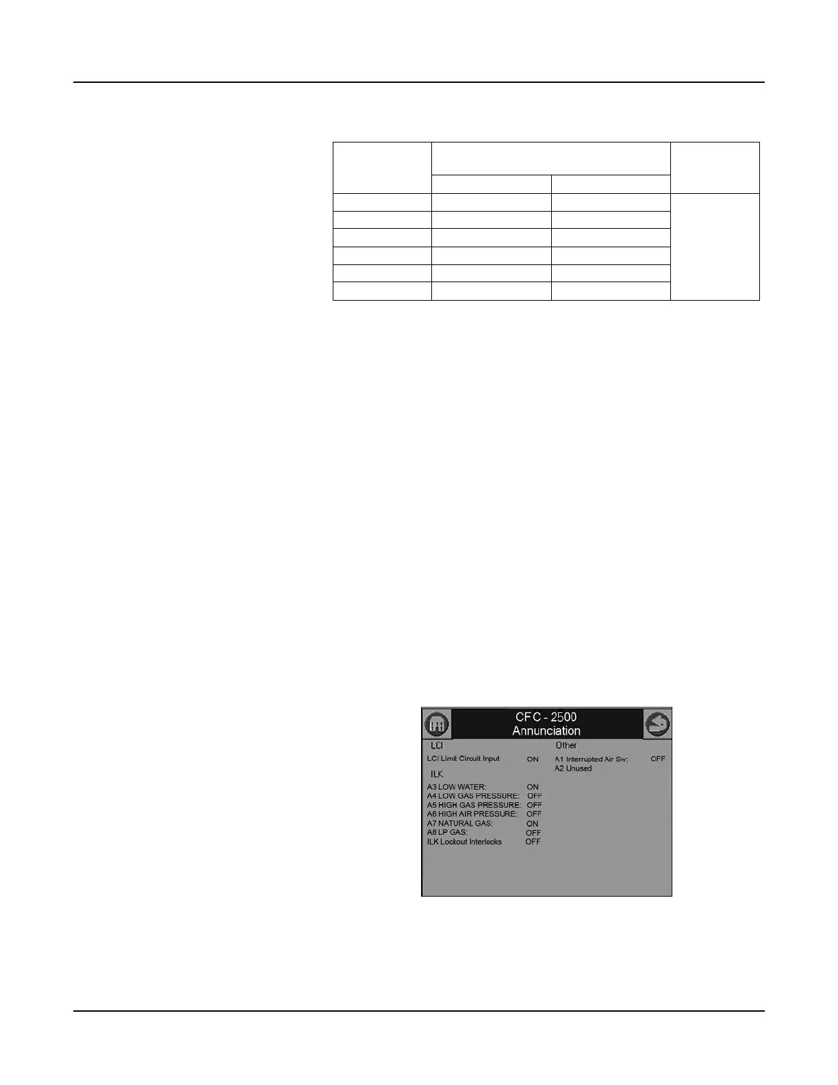
While performing the following safety checks, use the CB Falcon
Annunciation screen to monitor the status of the circuits involved.
Press <Annunciation> on the Operation page to access this screen.
LGPS
Table 4-2 Model CFC Gas Pressure Requirements
Boiler Model
Minimum pressure required at gas train
connection
Max. pressure
Natural Gas LP Gas
500 7" w.c. 11" w.c.
28” w.c.
750 7" w.c. 11" w.c.
1000 7" w.c. 11" w.c.
1500 10" w.c. 11" w.c.
1800 7" w.c. 11" w.c.
2500 9.5" w.c. 11" w.c.
Figure 4-5 Annunciation Screen