Section 1 — Introduction
Part No. 750-263 1-3
B. STANDARD EQUIPMENT
1. The Boiler
The boiler is designed for a Maximum Allowable Working Pressure
(MAWP) of 125 psig (8.6 Bar) in accordance with the ASME Code
for Low Pressure Section IV Hot Water Boilers and is stamped
accordingly. Operating pressure shall be less than 112 psig (7.7
Bar).
The vessel is mounted on a steel base with insulation & casing
provided including trim and controls. Trim and controls include
safety relief valve, pressure/temperature gauge, probe type low
water control, and CB Falcon hydronic boiler control with associated
sensors..
2. The Burner (See Figure 1-4)
Incorporating "premix" technology, the burner utilizes a venturi, dual
safety shutoff-single body gas valve, variable speed blower, and
Fecralloy metal fiber burner head.
Integral variable speed combustion air fan provides 5:1 turndown.
Combustion canister of the burner is constructed of a Fecralloy-
metal fiber for solid body radiation of the burner flame, which
provides low emissions.
At maximum firing rate, the sound level of the burner is less than
70 dBA, measured in front of the boiler at a distance of 3 feet.
Provision for direct vent combustion is furnished.
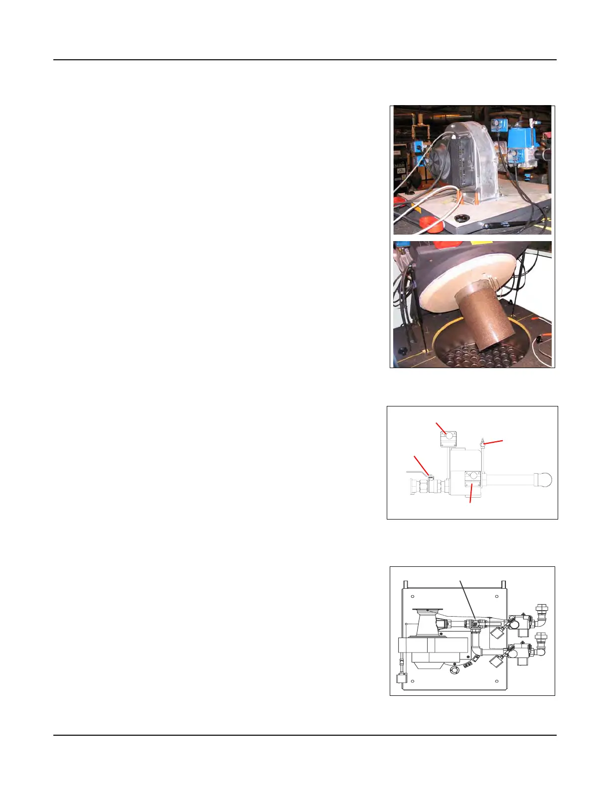
3. Burner Gas Train (See Figure 1-5 & Figure 1-6)
The gas train assembly is provided in accordance with UL
certification and complies with ASME CSD-1. The gas train
assembly is factory assembled and wired, consisting of the
following components:
A. Low Gas Pressure Switch - manual reset
B. High Gas Pressure Switch - manual reset
C. Single body, dual safety shutoff gas valve with integral trim
regulator
D. Integral Venturi
E. Manual Shutoff Ball Valve
F. C S D - 1 Te s t C o c k s
Figure 1-4 Burner
Figure 1-5 Standard Gas Train
High Gas Pressure Switch
Low Gas Pressure Switch
Manual Shutoff
Test C o ck
Figure 1-6 Optional dual gas train
Gas Shutoff / Selector Valve
Natural
Gas Train
Propane
Gas Train