Section 2 — Installation
Part No. 750-263 2-15
Clean combustion air is required for optimum efficiency and boiler
operation. Dust and airborne contaminants will adversely effect
burner performance. If conditions dictate, a serviceable filter must
be placed in the intake piping to eliminate airborne contamination
to the burner. An optional air filter is available from Cleaver-Brooks.
Additionally, if a direct vent combustion air intake vent is used the
intake should be directed to eliminate rain or snow from entering the
intake piping. The boiler must be installed so that the gas ignition
system components are protected from water (dripping, spraying,
etc.) during appliance operation and service.
F. GAS CONNECTIONS
1. General
The ClearFire Model CFC gas fired condensing boilers are full
modulating input units that require appropriate gas supply pressure
and volume for proper operation. The gas requirements specified in
this section must be satisfied to ensure efficient and stable
combustion. Installation must follow these guidelines and those of
any local authorities having installation jurisdiction.
2. Gas Train Components
CFC boilers are equipped with a gas train that meets the
requirements of ASME CSD-1, FM and XL-GAP (formerly IRI). The
gas train and its components have been designed and tested to
operate for the highest combustion efficiency for the CFC units.
3. Gas Pressure Requirements
For proper and safe operation, each CFC Series boiler requires a
stable gas pressure input. See Ta ble 2- 3 for pressure requirements.
Actual gas pressure should be measured when the burner is firing
using a manometer at the upstream test port connection on the
main gas valve. For a multiple unit installation, gas pressure should
be set for a single unit first, then the remaining units should be
staged on to ensure that gas pressure drop is not more than 1" w.c.
and never below the required pressure. Fluctuating gas pressure
readings could be indicative of a faulty supply regulator or improper
gas train size to the boiler.
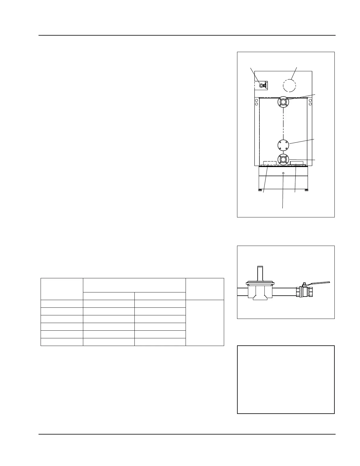
Figure 2-20 CFC Rear View
Gas
Connection
Air Inlet
Extension
Hot
Water
Out
Flue Gas
Vent Connection
Alternate
Flue Gas
High
Temp.
Return
Low
Temp.
Return
Condensate Drain
Figure 2-21 Gas Regulator and
Shutoff Valve (typical)
Gas Pressure Regulator
Shutoff Valve
Table 2-3 Model CFC Gas Pressure Requirements
Boiler Model
Minimum pressure required at gas train
connection
Max. pressure
Natural Gas LP Gas
500 7" w.c. 11" w.c.
28” w.c.
750 7" w.c. 11" w.c.
1000 7" w.c. 11" w.c.
1500 10" w.c. 11" w.c.
1800 7" w.c. 11" w.c.
2500 9.5" w.c. 11" w.c.
NOTE: The pressure test port is
located at the gas valve inlet
flange (see Figure 2-22). The
remaining test cocks are for leak
test purposes and should not be
used to measure gas pressure.
Refer to
APPENDIX C - GAS VALVE
INSTALLATION AND MAINTENANCE
for more information.