Section 2 — Installation
2-20 Part No. 750-263
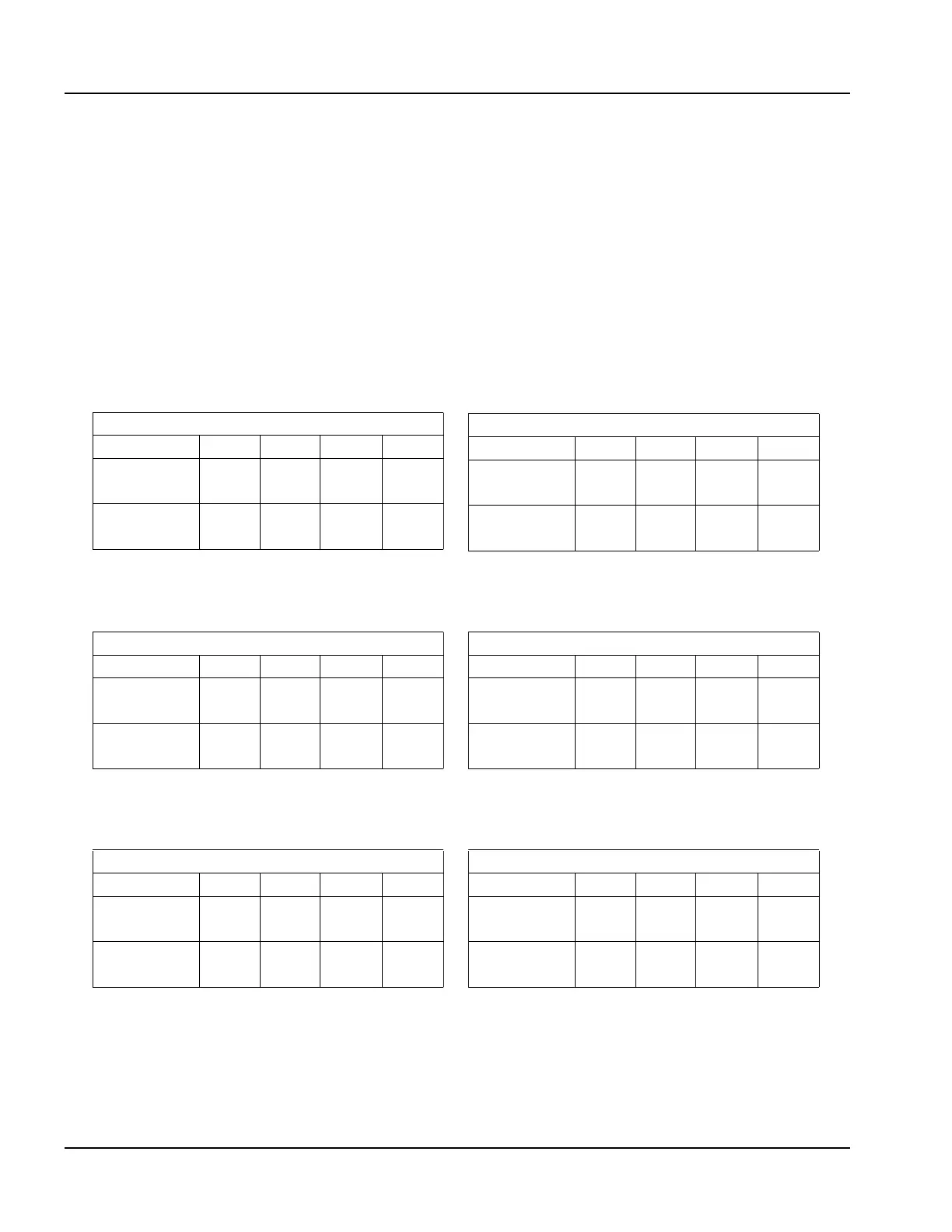
6. Gas Header
Design of a single common gas header with individual takeoffs for a
multiple unit installation is recommended. Boiler gas manifold
piping should be sized based on the volume requirements and
lengths between boilers and the fuel main header (see Figure 2-23).
Tab les 2-6 to 2-11 indicate the proper sizing for multiple units of
equal size, placed on the factory standard center with the noted
take off size. For installations with a mixed sized use, determine the
flow of each unit and total the input. With the total input, determine
length of run from the source and determine what size header will
be needed for the flow of all units firing. Pipe sizes based on Ta b le
2-4.
Table 2-6: Multiple Unit Manifold, CFC 500
Table 2-7: Multiple Unit Manifold, CFC 750
CFC 500 Boilers
# of Units 1 2 3 4
Pipe Size to
Boiler
1" 1" 1" 1"
Header Pipe
size
1-1/4" 1-1/4" 1-1/2" 2"
CFC 750 Boilers
# of Units 1 2 3 4
Pipe Size to
Boiler
1" 1" 1" 1"
Header Pipe
size
1-1/4" 1-1/2" 2" 2-1/2"
Table 2-8: Multiple Unit Manifold, CFC 1000 Table 2-9: Multiple Unit Manifold, CFC 1500
CFC 1000 Boilers
# of Units 1 2 3 4
Pipe Size to
Boiler
1-1/4" 1-1/4" 1-1/4" 1-1/4"
Header Pipe
size
1-1/4" 2" 2" 2-1/2"
CFC 1500 Boilers
# of Units 1 2 3 4
Pipe Size to
Boiler
1-1/2" 1-1/2" 1-1/2" 1-1/2"
Header Pipe
size
1-1/2" 2" 2-1/2" 3"
Table 2-10: Multiple Unit Manifold, CFC 1800 Table 2-11: Multiple Unit Manifold, CFC 2500
CFC 1800 Boilers
# of Units 1 2 3 4
Pipe Size to
Boiler
2" 2" 2" 2"
Header Pipe
size
2" 2-1/2" 3" 3"
CFC 2500 Boilers
# of Units 1 2 3 4
Pipe Size to
Boiler
2" 2" 2" 2"
Header Pipe
size
2" 3" 3" 4"