Section 2 — Installation
Part No. 750-263 2-31
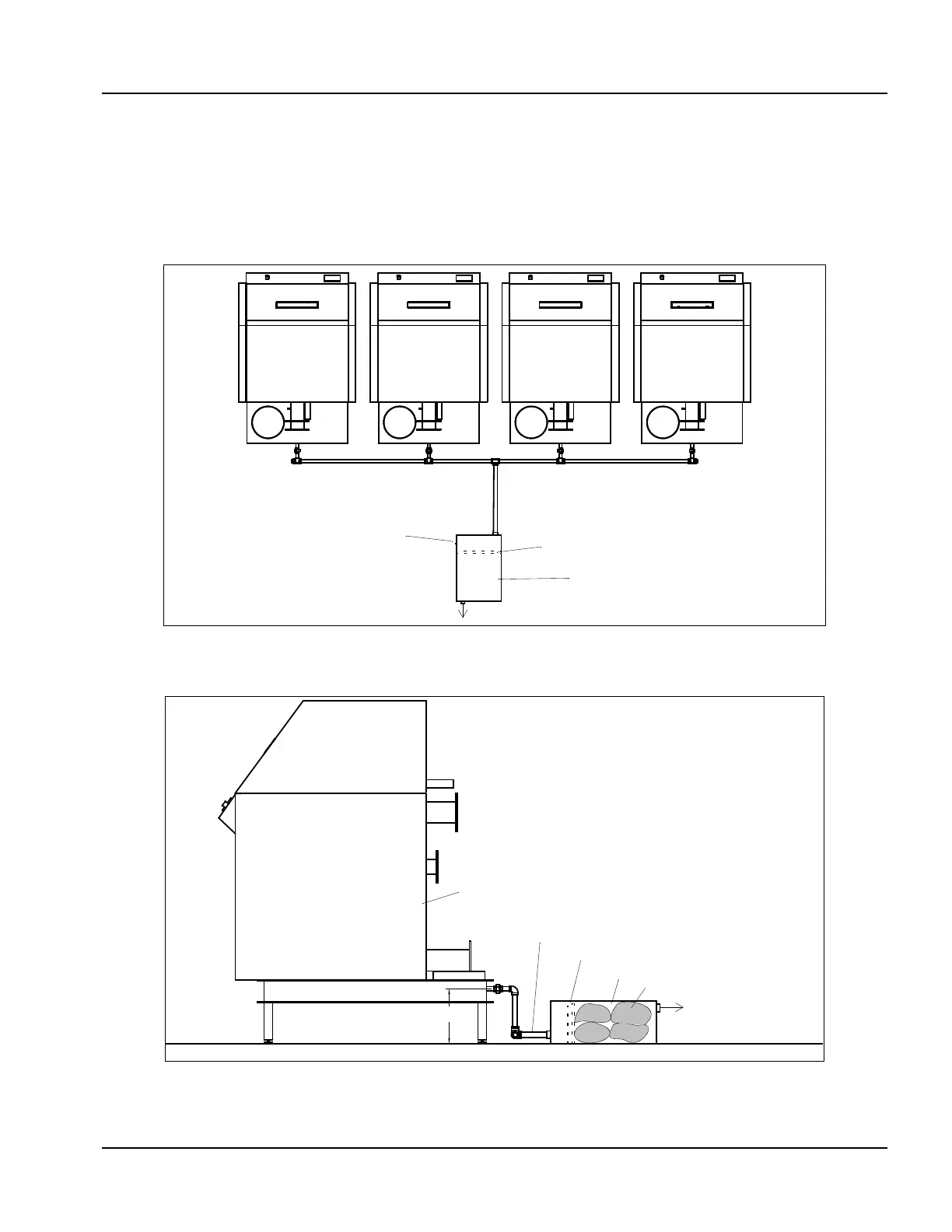
2. Condensate Piping for Multiple Boilers
More than one Model CFC boiler can be piped into a common
condensate neutralization tank. See Figure 2-39 and Figure 2-40
for the suggested layout. A drain trap is built into the condensate
tank. Make-up water must be supplied at the connection shown in
order to prevent flue gas from entering an idle boiler. An internal
float in the condensate tank activates the make-up water valve.
Figure 2-39 Condensate Piping for Multiple Boilers
Figure 2-40 Condensate Treatment Tank for Multiple Boilers
To Drain
1/4" O.D. Make-up Water Supply
Condensate Drain Trap
Neutralization Tank
To Drain
Condensate Drain Trap
1" NPT Minimum Header Size
(Use PVC Pipe or other Nonferrous Material)
Model CFC Boiler
Neutralization Tank
12" Minimum
Neutralization Media