Section 2 — Installation
Part No. 750-263 2-29
Table 2-13: Maximum flow rate through ClearFire boilers (metric flow rates)
H.CONDENSATE REMOVAL AND TREATMENT
The condensate generated during normal boiler operation must be
removed in accordance with local codes and regulations. The
condensate can be piped to a local treatment system or run into the
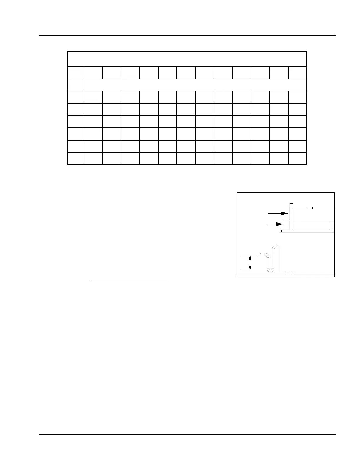
optional condensate treatment assembly. When piping condensate
direct to drain, a trap (Figure 2-36) must be installed on the
condensate outlet to prevent discharge of flue gases from the boiler.
When using the treatment tank, a drain trap is included in the tank
assembly and no external trap is required.
The water trap must be filled with water prior to commissioning and
checked or refilled at each required maintenance interval.
Notice
The condensate occurring during operation in both the boiler and the flue
gas pipeline has to be neutralized and piped to a safe drain. The conditions
for the discharge of condensates into public drain systems are determined
by the local authorities and municipalities.
Condensate leaving the boiler normally has a pH of 4-6. The
responsible authority will inform you if a higher pH value is required
for condensate piped to drain. The CFC neutralization system
contains the granulate NEUTRALAT, a natural compound which
acts to increase the pH of the condensate flowing through it. The
neutralization system comprises the plastic neutralization tank with
condensate inlet, makeup valve, drain trap, granulate chamber and
condensate outlet (see Figure 2-38). The system is installed in the
CFC lower collection area.
5 1117222733384550556164
500 21.6 10.9 7.5 5.4 4.3 3.6 2.7 2.5 2.3 2 1.8 1.6
750 29.75 15 10 7.5 6 5 4.3 3.6 3.4 2.9 2.7 2.5
1000 40 20 14 10 8 7 6 5 4.5 4 3.6 3.4
15005929.5201512108.47.56.665.45.2
180080402720161311.310 9 87.36.8
2500 106.7 53.4 36.7 26.8 21.6 17.9 15.2 13.4 11.8 10.9 9.8 8.8
Recommended flow rates relative to temperature drop so as not to exceed boiler output.
System Temperature Drop
0
C
Flow Rate m
3
/hr.
Boiler
Size
Figure 2-36 Flue Gas Trap 6 inch
Minimum Water Column
6”
Return Water In
Stack
Clearfire
Base