CB FALCON
53 750-265
PUMP CONTROL
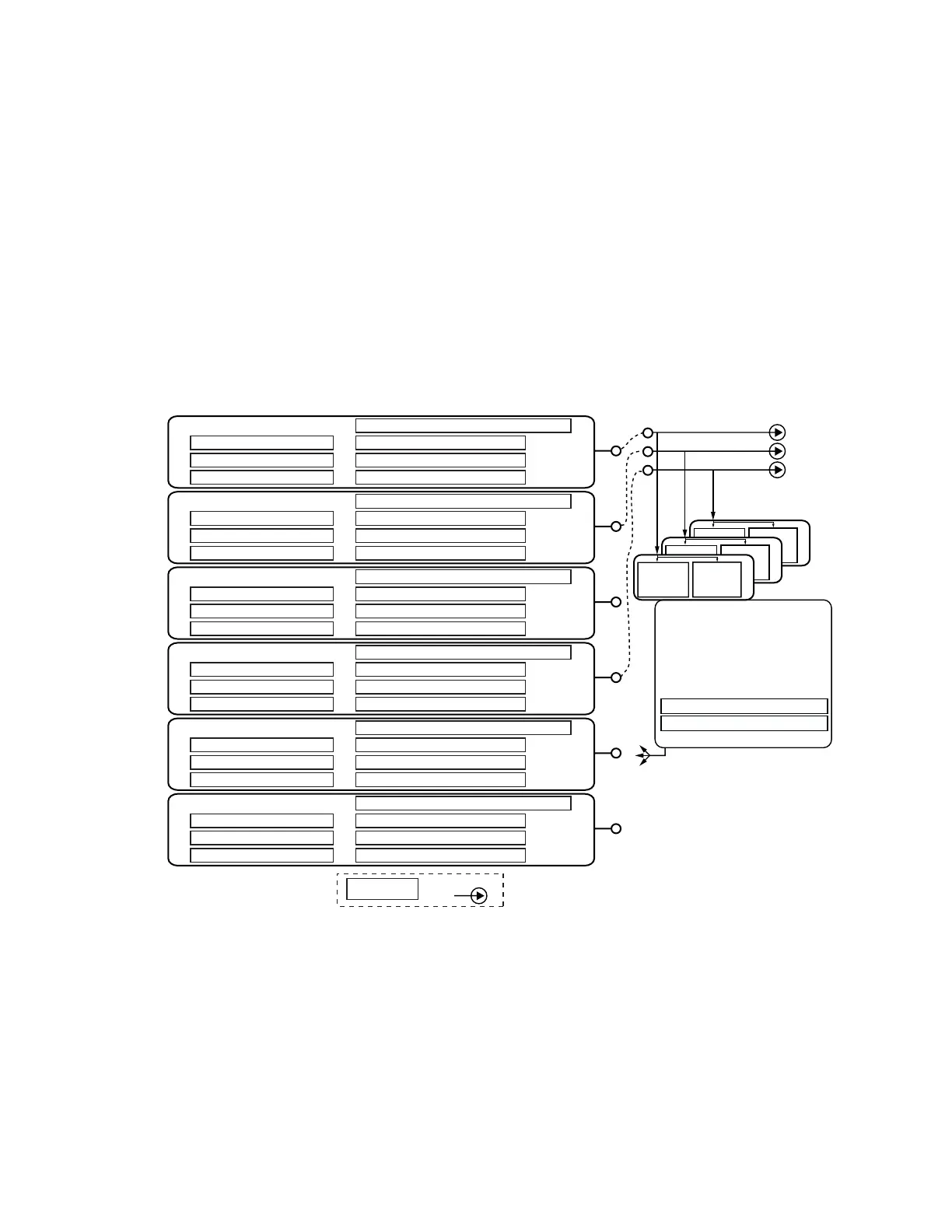
There are six identical pump control blocks. Each has a
different name but are entirely equal in features and
capabilities. For example, if the block named CH Pump were
configured to control the DHW pump and vice versa, and the
pumps were hooked up that way, both pumps would work
normally. Each can be configured for any purpose without
regard to the pump name. See Fig. 21.
The pump names are:
•Boiler
•CH
• DHW
•Aux1
•Aux2
• System
Pump control blocks can operate for a local Falcon, a LL
Master, or both. Some pump demands are always from the
local controller, some from the LL Master and some may come
from either source.
The pump overrun timers for frost protection are part of the
frost protection block, instead of the pump control block.
Fig. 21. Pump control blocks.
Pump Control Block Parameters
Each pump control block implements the parameters
described in Table 30, where “XX” is a placeholder for any of
the six pump names (CH, DHW, Boiler, System, Aux1, or
Aux2).
• Normal pump demand: These bits are in the lower left of
Fig. 22, and each of them enable or disable pump demand
that flows through the start delay and overrun time, to the
“On” connection of the physical device as shown in Fig. 22.
This form of pump demand may be inhibited by Force Off.
• Frost pump demand: These bits enable or disable frost
protection pump behavior, and these also flow to the “On
connection and thus may be inhibited by Force Off.
• Force Off conditions: These bits enable or disable
reasons why the pump may be forced off. The force Off
conditions flow to the “Force Off” connection to the pump
output block, and this signal inhibits the normal pump
demand and frost pump demand, but not the Force On
conditions.
PUMP C
RESET
IDLE DAYS
COUNTER
COUNT
CYCLE
COUNTER
PUMP B
RESET
IDLE DAYS
COUNTER
COUNT
CYCLE
COUNTER
CH PUMP OPTIONS 1
CH PUMP START DELAY
CH PUMP OVERUN TIME
CH PUMP OPTIONS 2
PUMP EXERCISE
CH PUMP CYCLE COUNT
CH PUMP CONTROL ON, AUTO
CH PUMP
PUMP CONTROL AND OPTIONS
DHW
PUMP OPTIONS 1
DHW PUMP START DELAY
DHW PUMP OVERUN TIME
DHW PUMP OPTIONS 2
DHW PUMP OUTPUT CONNECTION, A, B, C
CH PUMP OUTPUT CONNECTION, A, B, C
DHW PUMP CYCLE COUNT
DHW PUMP CONTROL ON, AUTO
DHW PUMP
BOILER PUMP OPTIONS 1
BOILER PUMP START DELAY
BOILER PUMP OVERUN TIME
BOILER PUMP OPTIONS 2
BOILER PUMP OUTPUT CONNECTION, A, B, C
BOILER PUMP CYCLE COUNT
BOILER PUMP CONTROL ON, AUTO
BOILER PUMP
SYSTEM PUMP OPTIONS 1
SYSTEM PUMP START DELAY
SYSTEM PUMP OVERUN TIME
SYSTEM PUMP OPTIONS 2
SYSTEM PUMP OUTPUT CONNECTION, A, B, C
SYSTEM PUMP CYCLE COUNT
SYSTEM PUMP CONTROL ON, AUTO
SYSTEM PUMP
AUX1 PUMP OPTIONS 1
AUX1 PUMP START DELAY
AUX1 PUMP OVERUN TIME
AUX1 PUMP OPTIONS 2
AUX1 PUMP OUTPUT CONNECTION, A, B, C
AUX1 PUMP CYCLE COUNT
AUX1 PUMP CONTROL ON, AUTO
AUX1 PUMP
AUX2 PUMP OPTIONS 1
AUX2 PUMP START DELAY
AUX2 PUMP OVERUN TIME
AUX2 PUMP OPTIONS 2
AUX2 PUMP OUTPUT CONNECTION, A, B, C
AUX2 PUMP CYCLE COUNT
AUX2 PUMP CONTROL ON, AUTO
PARAMETER
SEE PumpControlBlock.cvx FOR DETAILS ABOUT EACH PUMP CONRTOL BLOCK
PUMP A
PUMP EXERCISE INTERVAL (DAYS)
PUMP A
RESET
IDLE DAYS
COUNTER
COUNT
CYCLE
COUNTER
THERE ARE 6 PUMP CONTROL BLOCKS THAT ARE FUNCTIONALLY IDENTICAL EACH HAS
7 PARAMETERS THAT WORK THE SAME WAY IN EACH BLOCK. SEE PumpControlBlock.evx
DRAWING FOR DETAILS.
OUTPUT
AUX2 PUMP
PUMP B
PUMP C
IF A PUMP IS IN USE, I.E., IF IT
IS CONNECTED TO ANY
FUNCTION, AND IF IT HAS NOT
BEEN RUN FOR D DAYS, THEN
TURN IT ON FOR M MINUTES.
PARAMETERS
(COMMON TO ALL 4):
A FUNCTION (ON THE LEFT) MAY
EITHER BE CONNECTED TO ONE
PUMP OR NOT CONNECTED AT ALL.
IF NOT CONNECTED, IT HAS
NO EFFECT.
IF MULTIPLE FUNCTIONS ARE
CONNECTED TO THE SAME PUMP,
THEN IF EITHER FUNCTION WANTS
THE PUMP TO BE ON, IT WILL BE ON.
(I.E. A LOGICAL OR).
(EITHER OF THESE AS 0 DISABLES)
EXERCISE COMMANDS TO THE CONNECTED
FUNCTION(S). CYCLE COUNTS ARE VISIBLE
AS FUNCTIONAL PARAMETERS AND IDLE
DAYS COUNTS ARE VISIBLE AS
FUNCTION STATUS.
PUMP EXERCISE TIME (MINUTES)