CB FALCON
750-265 8
OVERVIEW
Functions provided by the Falcon include automatic boiler
sequencing, flame supervision, system status indication, firing
rate control, load control, CH/DHW control, limit control,
system or self-diagnostics and troubleshooting.
The maximum version of the controller offers:
• NTC-temperature sensor for:
• Outlet Limit And Temperature
• DHW (Domestic Hot Water) Limit and Temperature
• Stack Temperature Limit and Temperature
• Inlet Temperature
• Outdoor Temperature (hydronic only)
• Modulating output PWM-driven rotation speed controlled
DC-fan for optimal modulation control.
• Three Pump Outputs with 5 selectable operation modes
• 24Vac or 120Vac (model specific) offer:
• Output control of gas valve (Pilot and Main) and
External Ignition Transformer
• Digital inputs for room limit control, high limit control,
Air pressure switch, Gas pressure switch, low water
cutoff, valve proof of closure switch.
• Optional switches:
• Time of Day switch
• Burner switch
• Remote Reset
• Easy modification of the parameters on three levels:
• End-user
• Installer / Service engineer
• Manufacturer
• Integrated spark transformer
• Optional external spark transformer
• Optional combined ignition and flame sensing
• Test jacks for flame signal measurement from either a flame
rod or UV flame sensor.
• Alarm Output
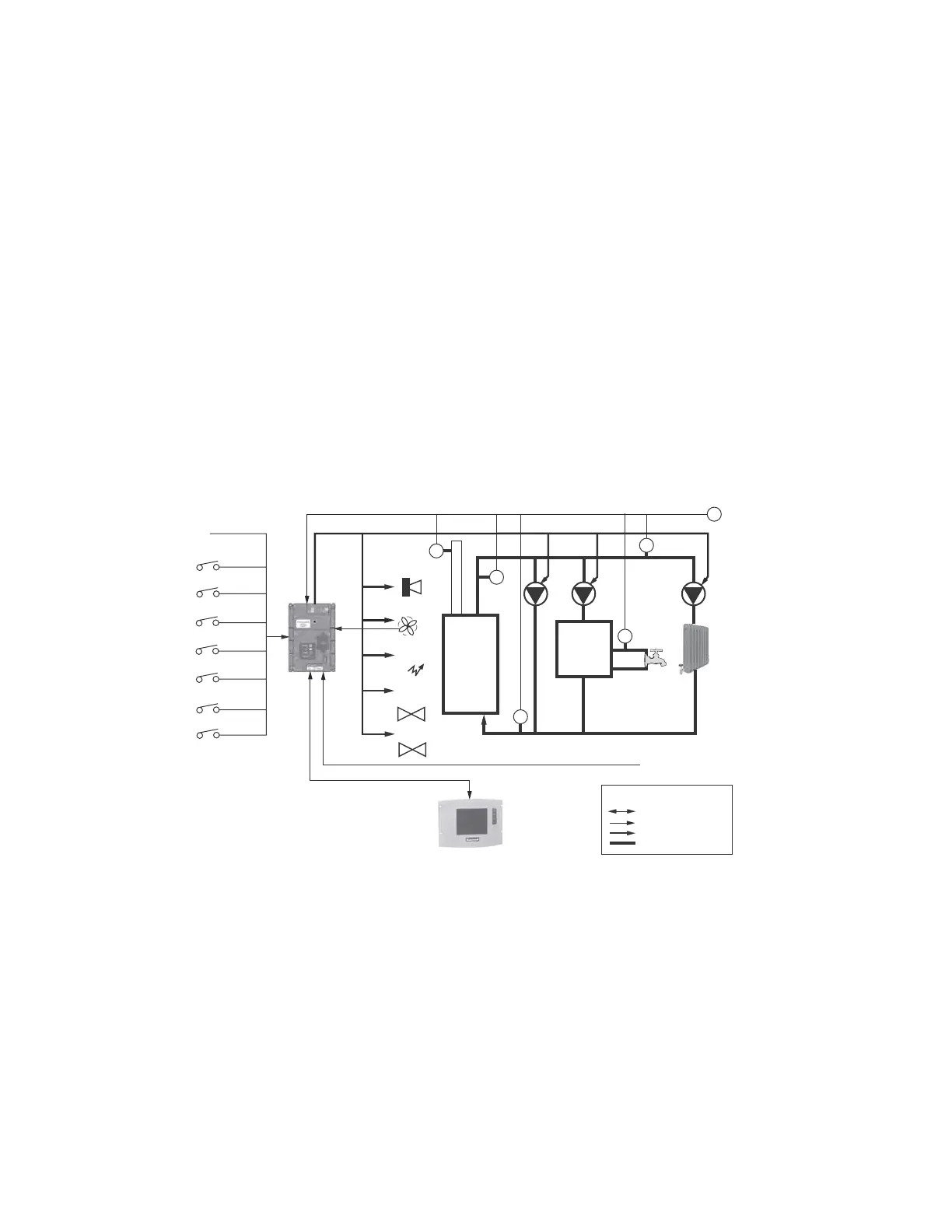
Fig. 1. General Falcon hydronic boiler schematic.
Fig. 1 shows two loops of heat control: Central Heating (CH),
and an optional second loop for Domestic Hot Water (DHW)
can be configured on each Falcon. The DHW loop transfers
heat from the boiler outlet to hot water appliances in
conjunction with the primary system heat loop. Priority
assignment to each heat loop can be configured to specify
which loop gets serviced first.
COMMUNICATIONS AND
DISPLAYS
• The Falcon has two RS485 communication ports for
Modbus that allows for interfacing to one or all Falcons in a
system and presents them individually to the user. The
System Operator interface is used for configuration and
monitoring of the CB Falcon. Control operation and display
status in both test and graphical modes can be shown. The
Falcon can also be remotely reset through the display.
• Either Modbus RS485 communication port can be used to
allow configuration and status data to be read and written to
the controller. A Building Automation master can control the
Falcon to respond to requests in a Lead/Lag arrangement.
Falcon
HEAT
LOAD
T
OUTDOOR
TEMP
T
HEADER
TEMP
IGNITOR
FAN
ALARM
STACK
T
T
BOILER
OUTLET
T
T
INLET
FLAME SIGNAL
INTERLOCK(S)
PII
LIMIT(S)
NNUNCIATION (8)
REMOTE RESET
TOD
STAT
PILOT
VALVE
MAIN VALVE(S)
DOMESTIC
HOT WATER
TANK
BOILER
MIX
LOOP
DHW
LOOP
M27058
BUILDING
AUTOMATION
SYSTEM
WATER
OUTPUTS
INPUTS
KEY
COMMUNICATION
SYSTEM
DISPLAY
CH
LOOP