CB FALCON
17 750-265
a
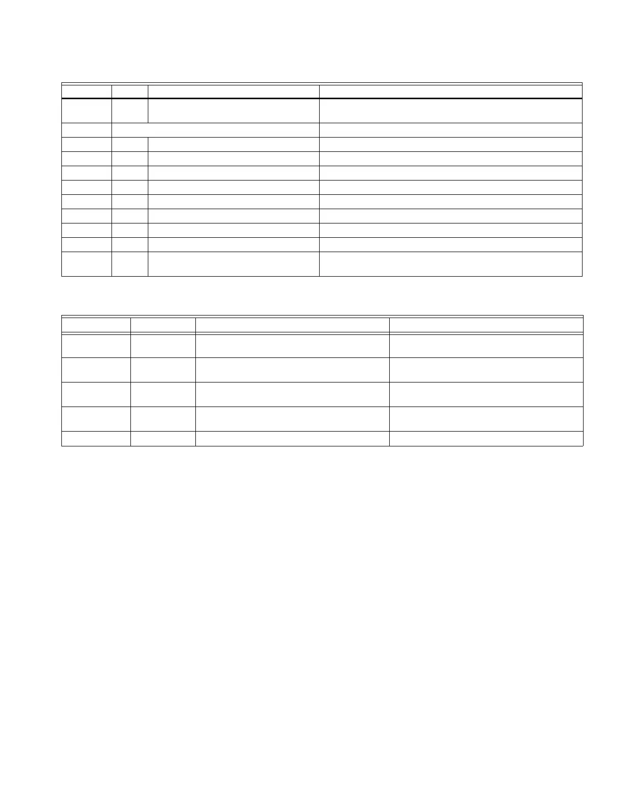
Not used by Falcon steam control
b
For single sensor 10K or 12K connect to TEMP A Terminals.
a
For Direct Burner Ignition (DBI) the main valve gets connected to J5 terminal 2.
E1 Spark 8kV minimum open circuit voltage; 2.8mJ
at the igniter
Plug In Module (PM7910)
1VCC
2CSO
3CS1
4SDA
5SCL
6GND
Flame + FS + Testpoint for Flame signal. 0 to 10 VDC
Flame - FS - Testpoint for Flame signal - Ground
reference.
Table 4. Valve Load Ratings.
Combination # Ignition Pilot Valve
a
Main Valve
a
1 No Load 180 VA Ignition + motorized valves with 660
VA inrush, 360 VA opening, 250 VA holding
65VA pilot duty + motorized valves with 3850
VA inrush, 700 VA opening, 250 VA holding
2 No Load 50VA Pilot Duty + 4.5A Ignition 65VA pilot duty + motorized valves with 3850
VA inrush, 700 VA opening, 250 VA holding
3 4.5A Ignition 65VA pilot duty + motorized valves with 3850
VA inrush, 700 VA opening, 250 VA holding
65VA pilot duty + motorized valves with 3850
VA inrush, 700 VA opening, 250 VA holding
4 4.5A Ignition 2A Pilot Duty 65VA pilot duty + motorized valves with 3850
VA inrush, 700 VA opening, 250 VA holding
5 4.5A Ignition 2A Pilot Duty 2A Pilot Duty
Table 3. Falcon Contact. (Continued)
Connector Term. Function Description and Rating (All Models)