CB FALCON
29 750-265
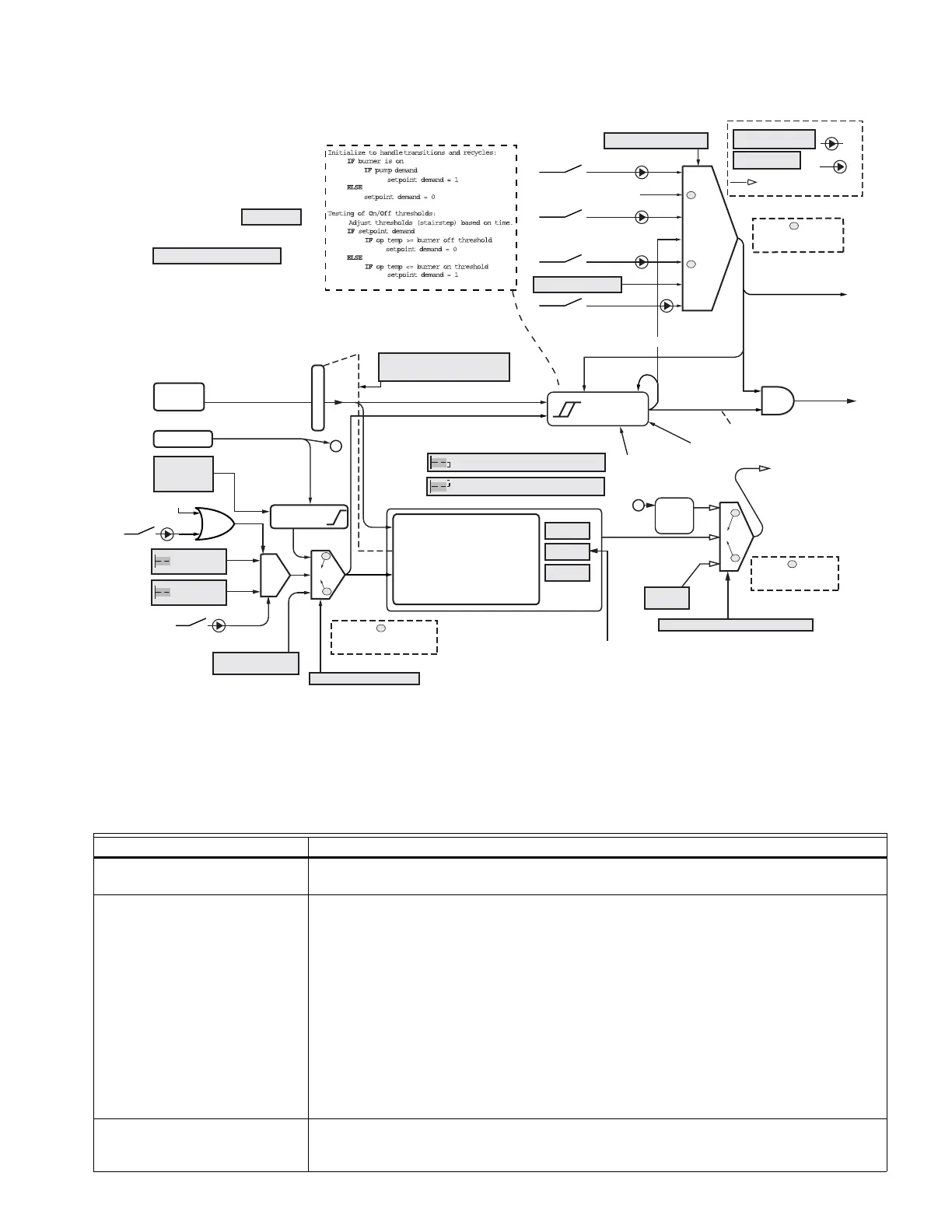
Fig. 11. Central heating steam diagram.
The function of each parameter and feature is given below.
.
CH BURNER
DEMAND
CH HEAT
DEMAND
CH MODULATION SENSOR
PRESSURE SENSOR TYPE:
0-15PSI OR 0-150PSI
MODBUS
STEAM SETPOINT
CH SETPOINT SOURCE
CH MODULATION RATE SOURCE
MODBUS
RATE
IGNORED: S1 IS ALWAYS USED AS
THE CH SENSOR FOR STEAM
CH DEMAND SWITCH
MODULUS STAT
PARAMETER
“pRATE” = 0 TO 99.99%
OF CAPACITY
INPUT
OUTPUT
CH ENABLE
STEAM HEATING
(CH)
CH
MINIMUM
PRESSURE
TOD
S2 4-20 mA
4-20 mA
TO SETPOINT
S1 INLET
4-20 mA
CH TOD
PRESSURE
SETPOINT
CH
PRESSURE
SETPOINT
CONVERSION
STEAM ONLY
PARAMETER
CH PRESSURE ON HYSTERESIS
CH PRESSURE OFF HYSTERESIS
A
A
P-GAIN
I-GAIN
D-GAIN
PID
RESTART (RESTART
INTEGRATOR WHENEVER
A LIMIT OR OVERRIDE
ENDS, OR TURN-ON
OCCURS.)
1 = S2 4-20mA REMOTE
2 = LOCAL
3 = MODBUS FUTURE
1 = S2 4-20mA
2 = LOCAL
3 = MODBUS 0-FF FUTURE
4 = MODBUS 0-200 FUTURE
1
2
3
ERROR SCALING:
PRESSURE ERROR IS
NORMALIZED:
1.0 PSI ERROR = 1.0˚C ERROR
FOR A 150 PSI SENSOR.
0.1 PSI ERROR = 1.0˚C ERROR
FOR A 15 PSI SENSOR.
WHERE = MEANS
“IS EQUIVALENT TO”
TIME SINCE:
BURNER TURN-ON
BURNER TURN-OFF
BURNER
STATE: ON/OFF
HYSTERESIS
STAT
EnviraCOM REMOTE STAT
LCI
STAT2
J7-3 120 VAC
FUTURE
FUTURE
FUTURE
SETPOINT DEMAND
SENSOR ONLY
1
2
3
4-20 mA
TO
pRATE
T
T
T
T
T
T
EnviraCOM TOD
TOD
NO DATA TIMEOUT
REVERT TO SETPOINT
T
NO DATA TIMEOUT
REVERT TO PID
NO DATA TIMEOUT
REVERT TO OFF
T
T
Table 10. Central Heating Steam Parameters.
Parameter Comment
Steam enable Disable, Enable
Disable/enable steam feature.
Steam demand source STAT and Sensor, Remote Stat and Sensor, LCI and Sensor, Sensor Only
The CH demand source may be selected from four options. In all cases, for burner demand
to exist, the sensor must be generating a demand as determined by setpoint and hysteresis
values.
• When “Sensor Only” is chosen, no other input is considered and pump demand is derived
from burner demand.
• When “STAT and Sensor” is chosen, the STAT input in the On condition creates pump
demand and it also must be on for burner demand to exist; if it is off there is no demand.
• When “Remote Stat and Sensor” is chosen, a message indicating the remote stat is on
creates pump demand and it also must be on for burner demand to exist; if the message
indicates this stat is off or if no message has been received within the message timeout
time (3–4 minutes), there is no demand.
• When “LCI and Sensor” is chosen, the LCI input in the On condition creates pump
demand and it also must be on for burner demand to exist; if it is off there is no demand.
Steam sensor Inlet
The sensor used for modulation and demand may be either the Outlet sensor, the 4-20mA
Inlet sensor.