climatemaster.com
25
Tranquility
®
Compact (TC) Series
Rev.: July 7, 2020
THE SMART SOLUTION FOR ENERGY EFFICIENCY
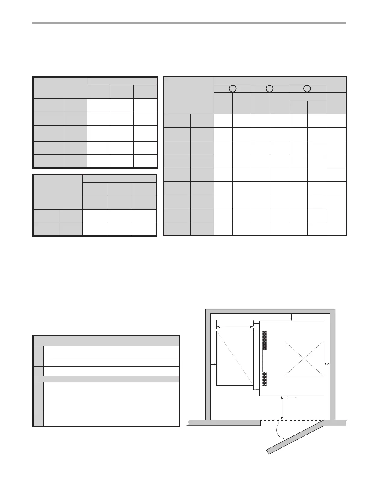
TC - Vertical Upow – Dimensional Data
Vertical
Upow
Model
Overall Cabinet
A
Width
B
Depth
C
Height
006 - 012
in
cm
19.1
48.5
19.1
48.5
22.0
55.9
015 - 018
in
cm
21.5
54.6
21.5
54.6
39.0
99.1
024 - 030
in
cm
21.5
54.6
21.5
54.6
40.0
101.6
036 - 042
in
cm
21.5
54.6
26.0
66.0
45.0
114.3
048 - 060
in
cm
24.0
61.0
32.5
82.6
46.0
116.8
Vertical
Upow
Model
Water Connections - Standard Units
1 2 3
Loop
In
D
Loop
In
E
Loop
Out
F
Loop
Out
G
Cond. 3/4” FPT
Loop
In/Out
FPT
H I
006 - 012
in
cm
1.4
3.6
1.6
4.1
9.5
24.1
1.6
4.3
6.1
15.6
1.6
4.1
1/2”
015
in
cm
1.9
4.8
1.4
3.6
13.8
35.1
1.4
3.6
8.1
20.6
1.4
3.6
1/2”
018
in
cm
1.9
4.8
1.4
3.6
12.9
32.8
1.4
3.6
8.1
20.6
1.4
3.6
1/2”
024
in
cm
1.9
4.8
1.4
3.6
13.8
35.1
1.4
3.6
8.1
20.6
1.4
3.6
3/4”
030
in
cm
1.9
4.8
1.4
3.6
15.2
38.6
1.4
3.6
8.1
20.6
1.4
3.6
3/4”
036
in
cm
1.9
4.8
1.4
3.6
15.7
39.9
1.4
3.6
8.1
20.6
1.4
3.6
3/4”
042
in
cm
1.9
4.8
1.4
3.6
16.6
42.0
1.4
3.6
8.1
20.6
1.4
3.6
3/4”
048
in
cm
1.9
4.8
1.4
3.6
16.6
42.2
1.4
3.6
8.1
20.6
1.4
3.6
1”
060
in
cm
1.9
4.8
1.4
3.6
17.2
43.7
1.4
3.6
8.1
20.6
1.4
3.6
1”
Recommended Minimum Installation Clearances for Vertical Units*
1”
Back of unit
Side opposite return air
6” Front if hard piped
Return Air Side
1”
Ducted return
- ‡
*Add for duct width
- † Add 2” for 1” lter frame/rail or 3” for 2” lter frame/rail
Free (open) return - calculate required dimension for a maximum
velocity of 600 fpm
*Field installed accessories (hoses, air cleaners, etc.) and factory WSE option will require addi-
tional space. Top supply air is shown, the same clearances apply to bottom supply air units.
Air Coil Side
Front
‡
†
1”
1”
1”
6”
*
Vertical
Model
Electrical Knockouts
J
1/2”
K
1/2”
L
3/4”
Low
Voltage
Low
Voltage
Power
Supply
006 - 012
in
cm
2.9
7.3
5.9
14.9
8.9
22.5
015 - 060
in
cm
4.1
10.5
7.1
18.1
10.1
25.7
Notes:
1. While clear access to all removable panels is not required, installer
should take care to comply with all building codes and allow
adequate clearance for future eld service.
2. Front & Side access is preferred for service access. However, all
components may be serviced from the front access panel if side
access is not available. (Except on TCV 009-030 with front return)
Units with the front return require left side access for the fan.
3. Discharge ange is eld installed.
4. Condensate is 3/4” FPT.
5. Units are shipped with air lter rails that are not suitable for
supporting return air ductwork. An air lter frame with duct mounting
collar is available as an accessory, see the Johnson Controls
Accessory Submittal set for futher information on this frame.
Legend:
CCP = Control/Compressor Access Panel
BSP = Blower Service Panel
ASP = Alternative Service Panel