ClimateMaster Water-Source Heat Pumps
34
CLIMATEMASTER WATER-SOURCE HEAT PUMPS
Tranquility
®
Compact (TC) Series
Rev.: July 7, 2020
Electrical – Line Voltage
CAUTION! Use only copper conductors for eld installed
electrical wiring. Unit terminals are not designed to accept
other types of conductors.
WARNING! Disconnect electrical power source to prevent
injury or death from electrical shock.
CAUTION!
WARNING!
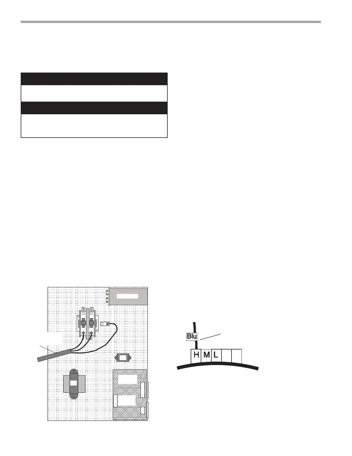
Figure 15: Single Phase Line Voltage Field Wiring.
Three phase wiring is similar except that all three
power wires are directly connected to the contactor.
Transformer
CXM
Control
Contactor -CC
BR
Low
Voltage
Connector
CB
L2
L1
Unit Power Supply
See electrical table for
breaker size
Grnd
Rev.: 5/17/01 B
Capacitor
Note: 460V units with ECM motor require a neutral wire.
Electrical - Line Voltage - All eld installed wiring,
including electrical ground, must comply with the National
Electrical Code as well as all applicable local codes. Refer
to the unit electrical data for fuse sizes. Consult wiring
diagram for eld connections that must be made by
the installing (or electrical) contractor. All nal electrical
connections must be made with a length of exible
conduit to minimize vibration and sound transmission to
the building.
General Line Voltage Wiring - Be sure the available
power is the same voltage and phase shown on the unit
serial plate. Line and low voltage wiring must be done in
accordance with local codes or the National Electric Code,
whichever is applicable.
Power Connection - Line voltage connection is made by
connecting the incoming line voltage wires to the “L” side
of the contractor as shown in Figure 15. Consult electrical
data tables for correct fuse size.
Transformer - All 208/230 voltage units are factory wired
for 208 volt. If supply voltage is 230 volt, installer must
rewire transformer. See wire diagram for connections.
Blower Speed Selection – Units with PSC Motor - PSC
(Permanent Split Capacitor) blower fan speed can be
changed by moving the blue wire on the fan motor
terminal block to the desired speed as shown in Figure
16. Most ClimateMaster units are shipped on the medium
speed tap. Consult submittal data or engineering design
guide for specic unit airow tables. Typical unit design
delivers rated airow at nominal static (0.15 in. w.g.
[37Pa]) on medium speed and rated airow at a higher
static (0.4 to 0.5 in. w.g. [100 to 125 Pa]) on high speed
for applications where higher static is required. Low speed
will deliver approximately 85% of rated airow at 0.10 in.
w.g. [25 Pa]. An optional high static blower is available on
some models.
Special Note for AHRI Testing: To achieve rated
airow for AHRI testing purposes on all PSC products,
it is necessary to change the fan speed to “HI” speed.
When the heat pump has experienced less than 100
operational hours and the coil has not had sufcient time
to be “seasoned”, it is necessary to clean the coil with a
mild surfactant such as Calgon to remove the oils left by
manufacturing processes and enable the condensate to
properly “sheet” off of the coil.
HML
Azul
Fan Motor
Motor del Ventilador
Conectar el cable azul a:
H para velocidad de ventilador alta
M para velocidad de ventilador media
L para velocidad de ventilador baja
La configuración de fábrica es velocidad
media
Connect the blue wire to:
H for High speed fan
M for Medium speed fan
L for Low speed fan
Medium is factory setting
Figure 16: PSC Motor Speed Selection