P/N 92974, Rev. 1 Page 41
3.4.2 Setting the feed rate
The feed rate is adjusted by an
adjusting screw. Each feed rate is
independent of the other; FORWARD
and REVERSE have separate feed
adjusting knobs.
The feed rate operates by the fol-
lowing rules:
• Turning the knob counter-clockwise (out) increases the feed rate.
• Turning the knob clockwise (in) decreases the feed rate.
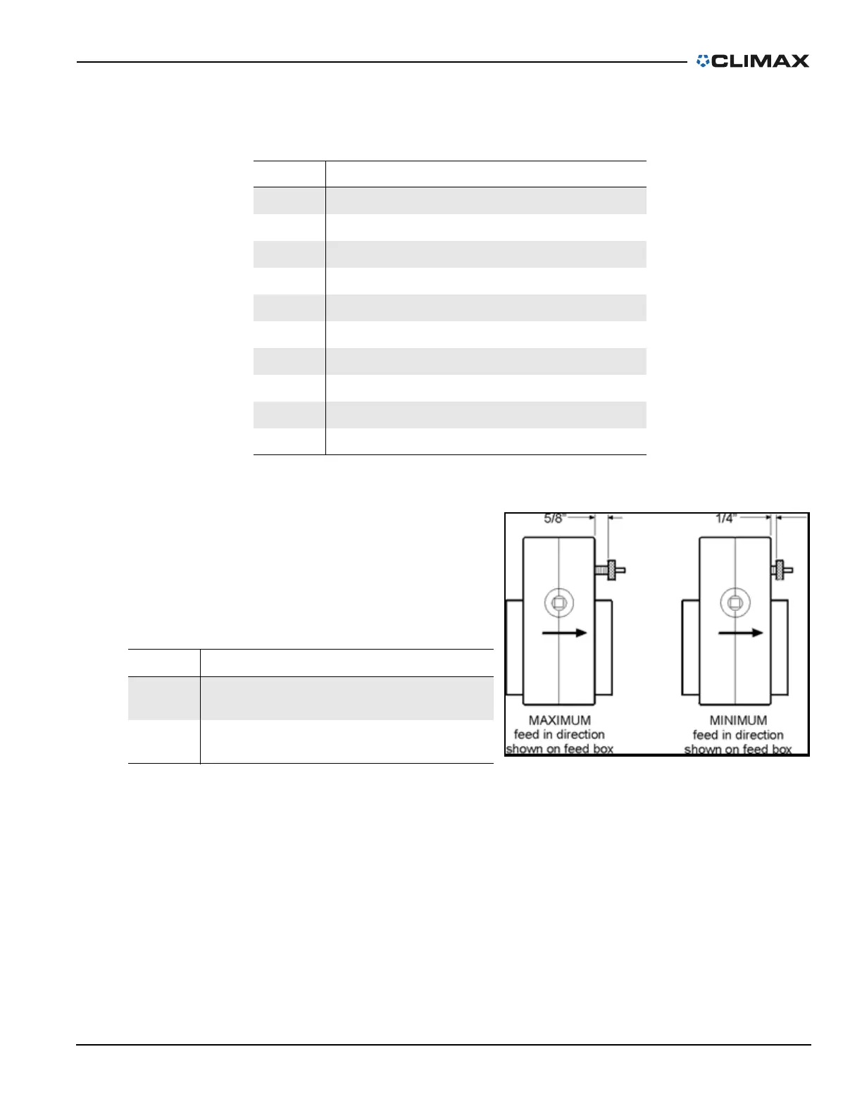
• The feed range is up to 0.018" (0.45 mm) per revolution of the bar.
• Maximum feed is reached when the knob is approximately 0.625" (16
mm) away from the feed box.
• Minimum feed is reached when the knob completely collapses the
compression spring approximately 0.25" (6 mm).
TABLE 3-6. AFU COMPONENT IDENTIFICATION
Number Component
1 Arrow #1
2 Push to feed in direction of arrow #1
3 Feed shaft
4 Feed stop pin
5 Feed adjusting knob for direction #1
6 Auto-stop arm assembly
7 Pin
8 Push to feed in direction of arrow #2
9 Drive bushing
10 Arrow #2
TABLE 3-7. FEED BOX ARROW IDENTIFICATION
Number Component
1
Maximum (feeds in the direction shown on
the feed box)
2
Minimum (feeds in the direction shown on
the feed box)
FIGURE 3-13. FEED BOX ARROWS