P/N 92974, Rev. 1 Page 35
9. Mount the tack weld plates
to the spherical bearing
mounting brackets. If more
clearance is required, weld
1" x 1" x 6" (12 mm x 12
mm x 72 mm) the tack weld
blocks to the tack weld mounting spacer plates.
10. Temporarily clamp the bracket assemblies to the workpiece. Leave enough
room to remove the cones after the brackets are welded in place.
11. Check that the setup cones are still securely in position.
12. Securely weld all standoffs and brackets in place.
13. Remove the temporary clamps.
14. Loosen the set screws in the setup cones.
15. Remove the bar from the brackets and remove the setup cones.
16. Carefully reinstall the bar through the mounting brackets.
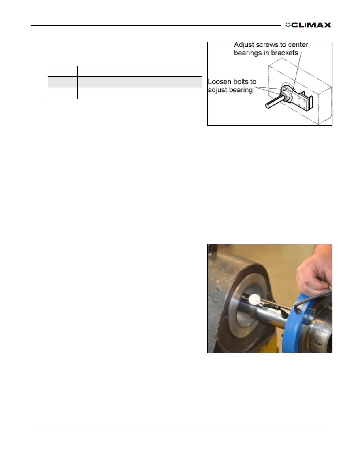
If necessary, precisely align the bar
by doing the following:
1. Loosen the hex bolts hold-
ing the bearing to the
bracket.
2. Attach a dial indicator to
the bar and touch the stylus
to the workpiece ID.
3. Rotating the bar, adjust the
set screws to center the bar.
4. Tighten the hex bolts to
keep the bearing and the bar
in place.
3.3.2 Tooling and tool head assembly
These machines are designed to cover a wide range of boring applications. The bar
design allows for inserting a tool bit into the bar or clamping a tool head assembly
TABLE 3-3. SPHERICAL BEARING IDENTIFICATION
Number Component
1 Loosen bolts to adjust bearing
2 Adjust screws to center bearings in brackets
FIGURE 3-5. POSITIONING THE SPHERICAL BEARINGS
FIGURE 3-6. ALIGNING THE BAR