Page 34 BB4500-BB5000 Operating Manual
3. Slide a setup cone (or a sub-
stitute device) onto each
end of the bar to center the
bar in the bore.
4. Tighten the set screw to
secure one of the cones.
5. While pulling on the bar
from the opposing end to seat the first cone, slide the second cone snug into
place. Tighten the set screw.
6. Mount the clamp collar next to one setup cone. Loosen the set screw in the
cone and drive it into the bore using the socket-head jacking screw. Tighten
the set screw in the setup cone to hold it securely in place.
7. Repeat step 3 through step 6 until the cones are seated in the bores and
there is no bar movement.
8. Center the spherical bearings in the mount-
ing brackets by doing the following:
a) Loosen the hex bolts.
b) Adjust the four set screws until the
bearing is centered.
c) Tighten the hex bolts.
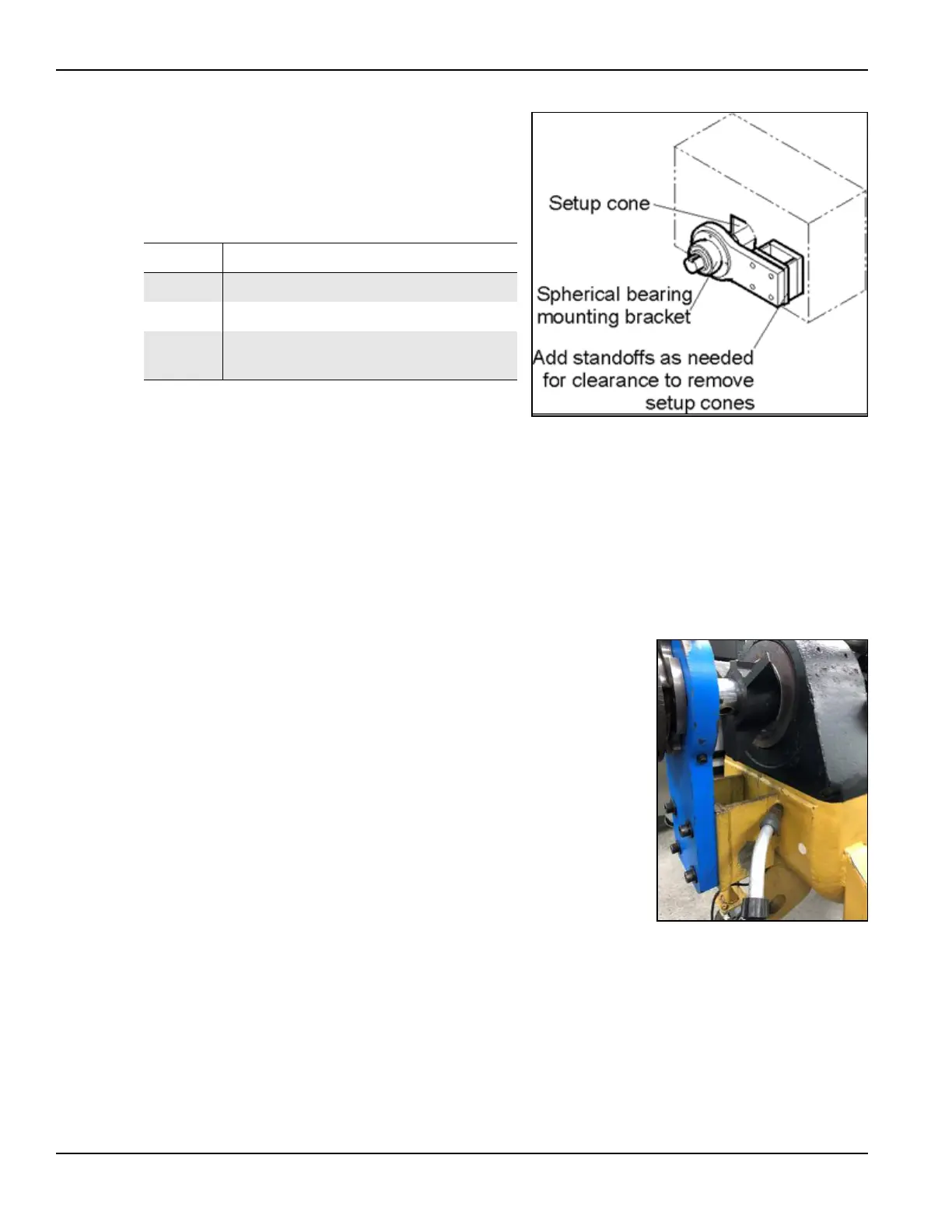
TABLE 3-2. SETUP CONE INSTALLATION IDENTIFICATION
Number Component
1 Setup cone
2 Spherical bearing mounting bracket
3
Standoffs (add as needed for clearance
to remove the setup cones)
FIGURE 3-3. SETUP CONE INSTALLATION
FIGURE 3-4. CENTERING THE SPHERI-
CAL BEARINGS