Repair procedures, tests, and adjustments
Manpack Transceiver 2110 series Repair Guide 91
1 Disconnect the sensor by easing the large 5-pin connector away from the PCB.
1 Replace the battery cells with equivalent rechargeable battery cells.
1 Combine the battery cells together in the same orientation and with the same
connections as the original battery cells.
1 Remove the resistor and cable assembly from the original battery cells and connect
this into the new arrangement of battery cells in the same position and orientation.
1 Place the battery cells into the foam lining inside the battery pack.
1 Reconnect the 5-pin sensor connector.
1 Reconnect the red wire to the + terminal.
1 Reconnect the black wire to the – terminal.
1 Rotate the head of the arrow on the rotary switch to position F to reset the battery
data.
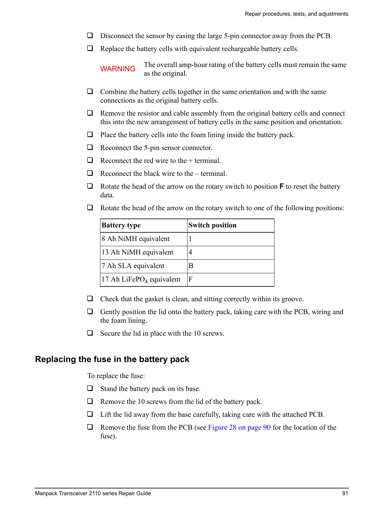
1 Rotate the head of the arrow on the rotary switch to one of the following positions:
1 Check that the gasket is clean, and sitting correctly within its groove.
1 Gently position the lid onto the battery pack, taking care with the PCB, wiring and
the foam lining.
1 Secure the lid in place with the 10 screws.
Replacing the fuse in the battery pack
To replace the fuse:
1 Stand the battery pack on its base.
1 Remove the 10 screws from the lid of the battery pack.
1 Lift the lid away from the base carefully, taking care with the attached PCB.
1 Remove the fuse from the PCB (see Figure 28 on page 90 for the location of the
fuse).
WARNING
The overall amp-hour rating of the battery cells must remain the same
as the original.
Battery type Switch position
8 Ah NiMH equivalent 1
13 Ah NiMH equivalent 4
7 Ah SLA equivalent B
17 Ah LiFePO
4
equivalent F
 Loading...


