Overview
18 Manpack Transceiver 2110 series Repair Guide
Battery pack
Figure 9: Front view of the battery pack
Pinouts of the battery connector on the battery pack
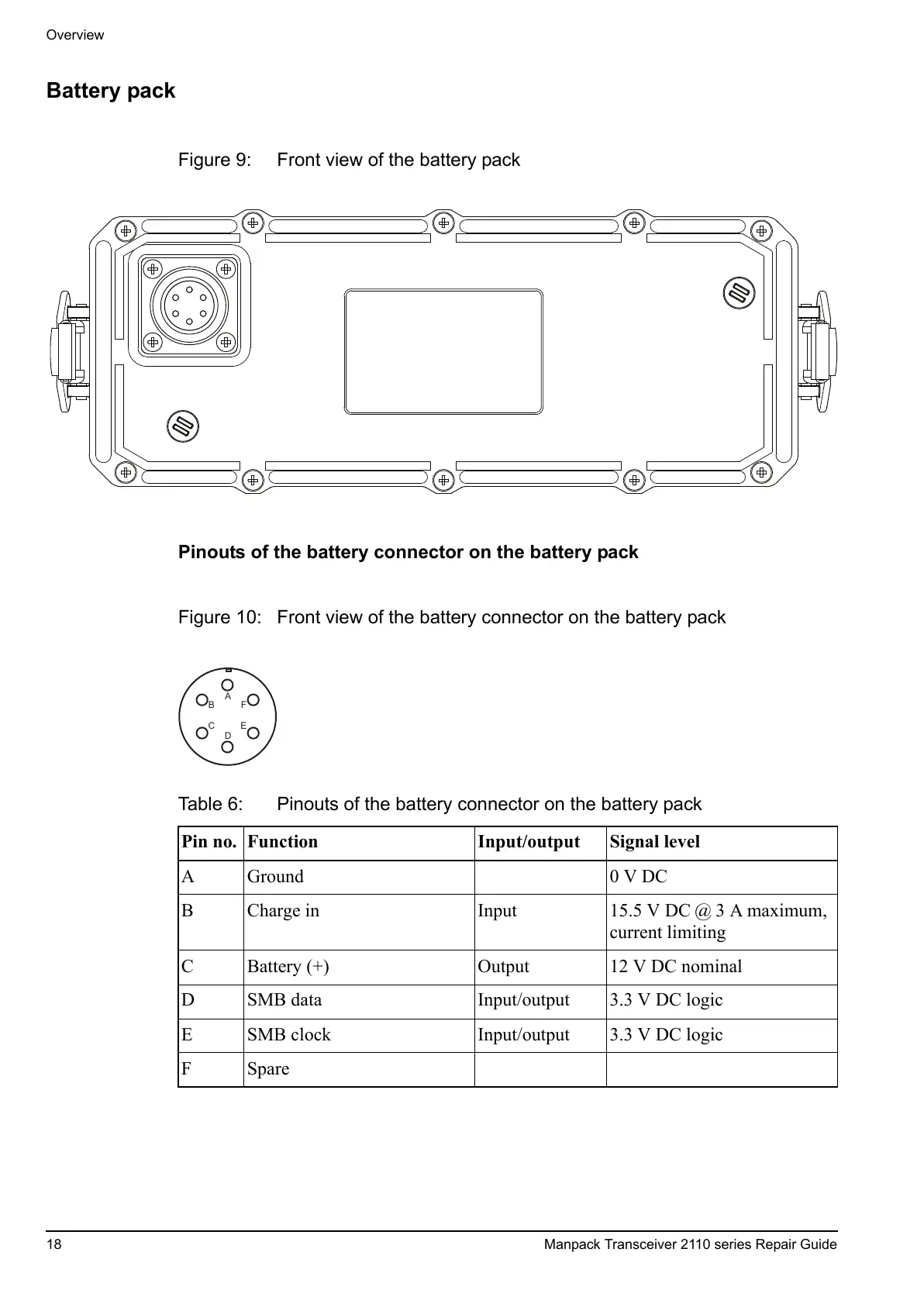
Figure 10: Front view of the battery connector on the battery pack
Table 6: Pinouts of the battery connector on the battery pack
Pin no. Function Input/output Signal level
A Ground 0 V DC
B Charge in Input 15.5 V DC @ 3 A maximum,
current limiting
C Battery (+) Output 12 V DC nominal
D SMB data Input/output 3.3 V DC logic
E SMB clock Input/output 3.3 V DC logic
FSpare
 Loading...


