Repair procedures, tests, and adjustments
Manpack Transceiver 2110 series Repair Guide 53
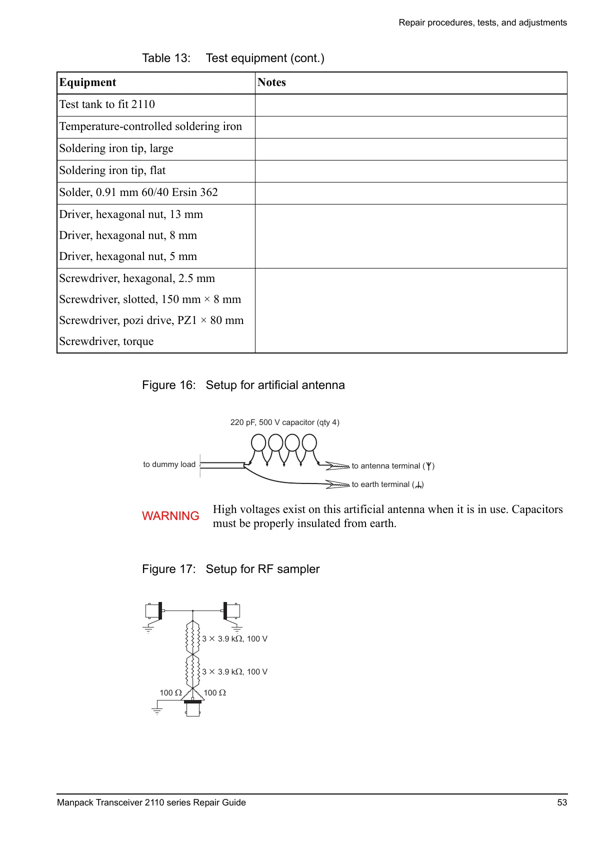
Figure 16: Setup for artificial antenna
Figure 17: Setup for RF sampler
Test tank to fit 2110
Temperature-controlled soldering iron
Soldering iron tip, large
Soldering iron tip, flat
Solder, 0.91 mm 60/40 Ersin 362
Driver, hexagonal nut, 13 mm
Driver, hexagonal nut, 8 mm
Driver, hexagonal nut, 5 mm
Screwdriver, hexagonal, 2.5 mm
Screwdriver, slotted, 150 mm × 8 mm
Screwdriver, pozi drive, PZ1 × 80 mm
Screwdriver, torque
WARNING
High voltages exist on this artificial antenna when it is in use. Capacitors
must be properly insulated from earth.
Table 13: Test equipment (cont.)
Equipment Notes

 Loading...


