Repair procedures, tests, and adjustments
52 Manpack Transceiver 2110 series Repair Guide
Test equipment
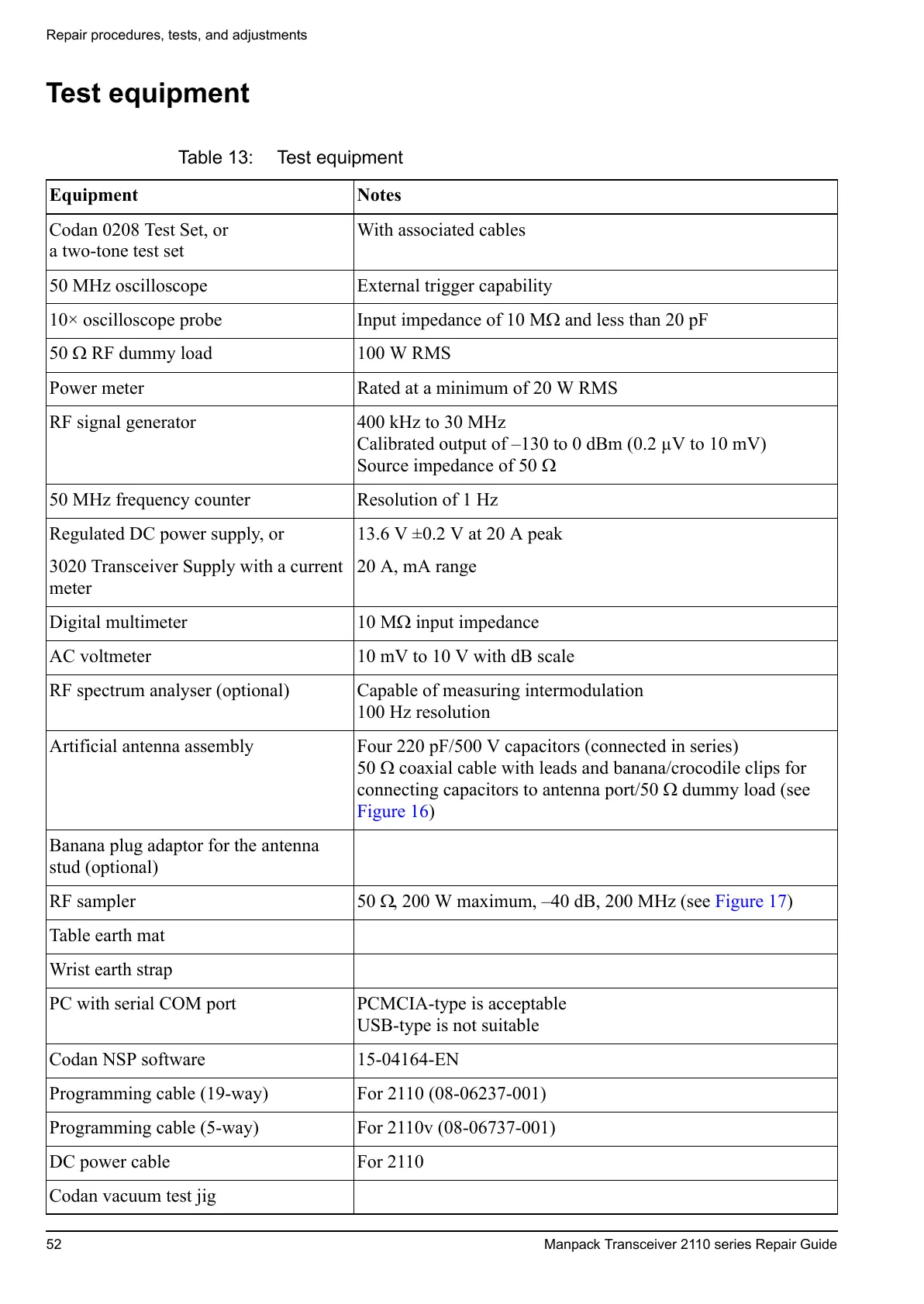
Table 13: Test equipment
Equipment Notes
Codan 0208 Test Set, or
a two-tone test set
With associated cables
50 MHz oscilloscope External trigger capability
10× oscilloscope probe Input impedance of 10 M and less than 20 pF
50 RF dummy load 100 W RMS
Power meter Rated at a minimum of 20 W RMS
RF signal generator 400 kHz to 30 MHz
Calibrated output of –130 to 0 dBm (0.2 µV to 10 mV)
Source impedance of 50
50 MHz frequency counter Resolution of 1 Hz
Regulated DC power supply, or
3020 Transceiver Supply with a current
meter
13.6 V ±0.2 V at 20 A peak
20 A, mA range
Digital multimeter 10 M input impedance
AC voltmeter 10 mV to 10 V with dB scale
RF spectrum analyser (optional) Capable of measuring intermodulation
100 Hz resolution
Artificial antenna assembly Four 220 pF/500 V capacitors (connected in series)
50 coaxial cable with leads and banana/crocodile clips for
connecting capacitors to antenna port/50 dummy load (see
Figure 16)
Banana plug adaptor for the antenna
stud (optional)
RF sampler 50 , 200 W maximum, –40 dB, 200 MHz (see Figure 17)
Table earth mat
Wrist earth strap
PC with serial COM port PCMCIA-type is acceptable
USB-type is not suitable
Codan NSP software 15-04164-EN
Programming cable (19-way) For 2110 (08-06237-001)
Programming cable (5-way) For 2110v (08-06737-001)
DC power cable For 2110
Codan vacuum test jig
 Loading...


