Repair procedures, tests, and adjustments
Manpack Transceiver 2110 series Repair Guide 71
1 Reconnect the coaxial cable to the 50 connector ( ).
1 Return to the Repair flowchart (see Figure 29 on page 95).
Performing the RF Output Power test
To test the RF output power of the transceiver:
1 Set up the equipment (see page 56, Setting up the test equipment).
1 Select any frequency between 4 and 6 MHz.
1 Switch on PTT on the 0208.
1 Adjust the output level of the 0208 until the RF output power of the transceiver stops
increasing, then increase the output level of the 0208 by 10 dB.
1 Record your results and actions (see page 109, Test sheet for the 2110 series
Manpack Transceiver).
1 For each band, adjust the output level of the 0208 until the RF output power of the
transceiver stops increasing, then increase the output level of the 0208 by 10 dB.
1 Record your results and actions (see page 109, Test sheet for the 2110 series
Manpack Transceiver).
1 Switch off PTT on the 0208.
1 Return to the Repair flowchart (see Figure 29 on page 95).
Pass A reading on the RF power meter that is between 20 and 25 W PEP.
NOTE
Equivalent readings for power meters without PEP and dB scales are
listed in Table 16.
Pass A reading on the RF power meter that is between 20 and 25 W PEP
for each band.
NOTE
Equivalent readings for power meters without PEP and dB scales are
listed in Table 16.
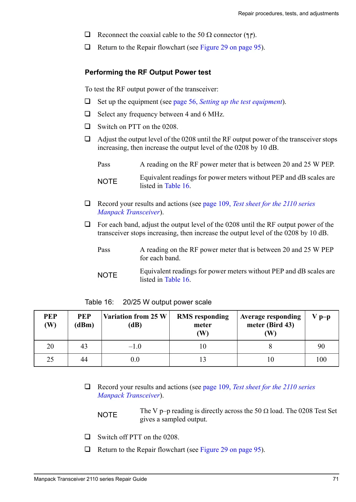
Table 16: 20/25 W output power scale
PEP
(W)
PEP
(dBm)
Variation from 25 W
(dB)
RMS responding
meter
(W)
Average responding
meter (Bird 43)
(W)
Vp–p
20 43 –1.0 10 8 90
25 44 0.0 13 10 100
NOTE
The V p–p reading is directly across the 50 load. The 0208 Test Set
gives a sampled output.
 Loading...


