Repair procedures, tests, and adjustments
56 Manpack Transceiver 2110 series Repair Guide
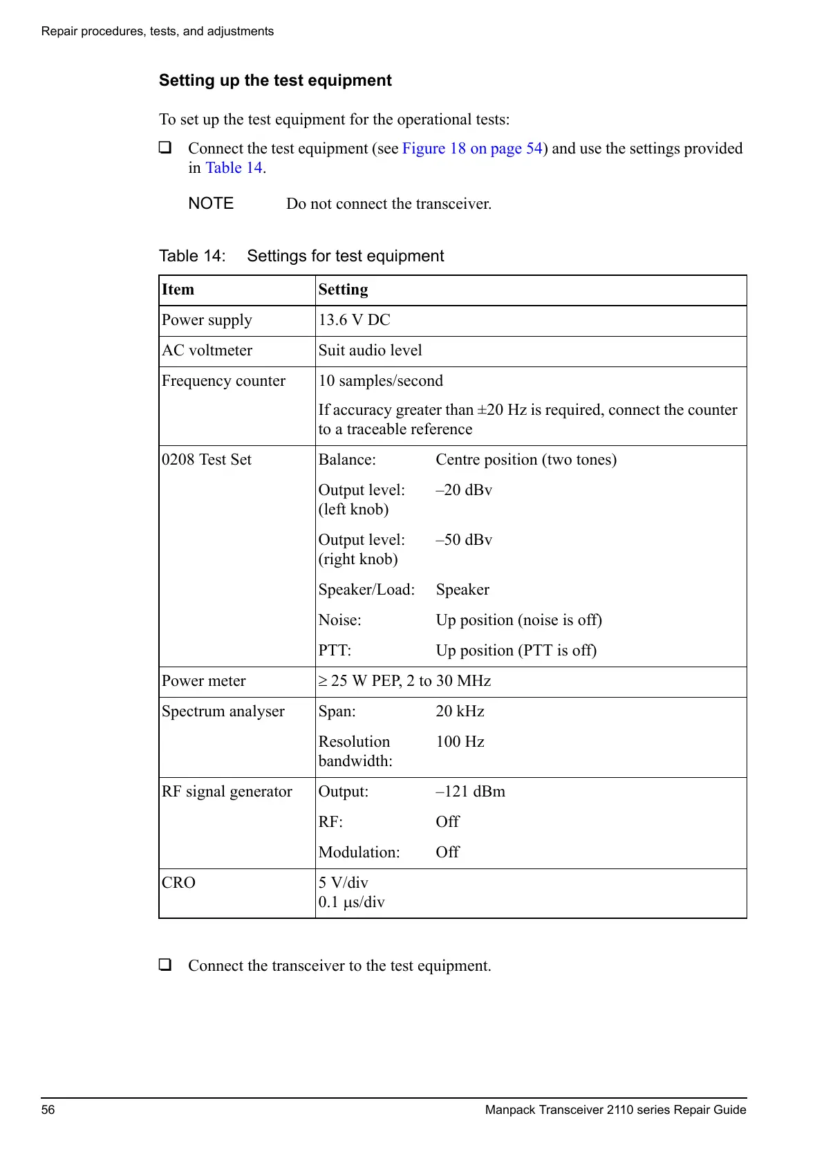
Setting up the test equipment
To set up the test equipment for the operational tests:
1 Connect the test equipment (see Figure 18 on page 54) and use the settings provided
in Table 14.
1 Connect the transceiver to the test equipment.
NOTE Do not connect the transceiver.
Table 14: Settings for test equipment
Item Setting
Power supply 13.6 V DC
AC voltmeter Suit audio level
Frequency counter 10 samples/second
If accuracy greater than ±20 Hz is required, connect the counter
to a traceable reference
0208 Test Set Balance: Centre position (two tones)
Output level:
(left knob)
–20 dBv
Output level:
(right knob)
–50 dBv
Speaker/Load: Speaker
Noise: Up position (noise is off)
PTT: Up position (PTT is off)
Power meter 25 W PEP, 2 to 30 MHz
Spectrum analyser Span: 20 kHz
Resolution
bandwidth:
100 Hz
RF signal generator Output: –121 dBm
RF: Off
Modulation: Off
CRO 5 V/div
0.1 s/div
 Loading...


