Overview
14 Manpack Transceiver 2110 series Repair Guide
Pinouts of the 19-way GPIO connector
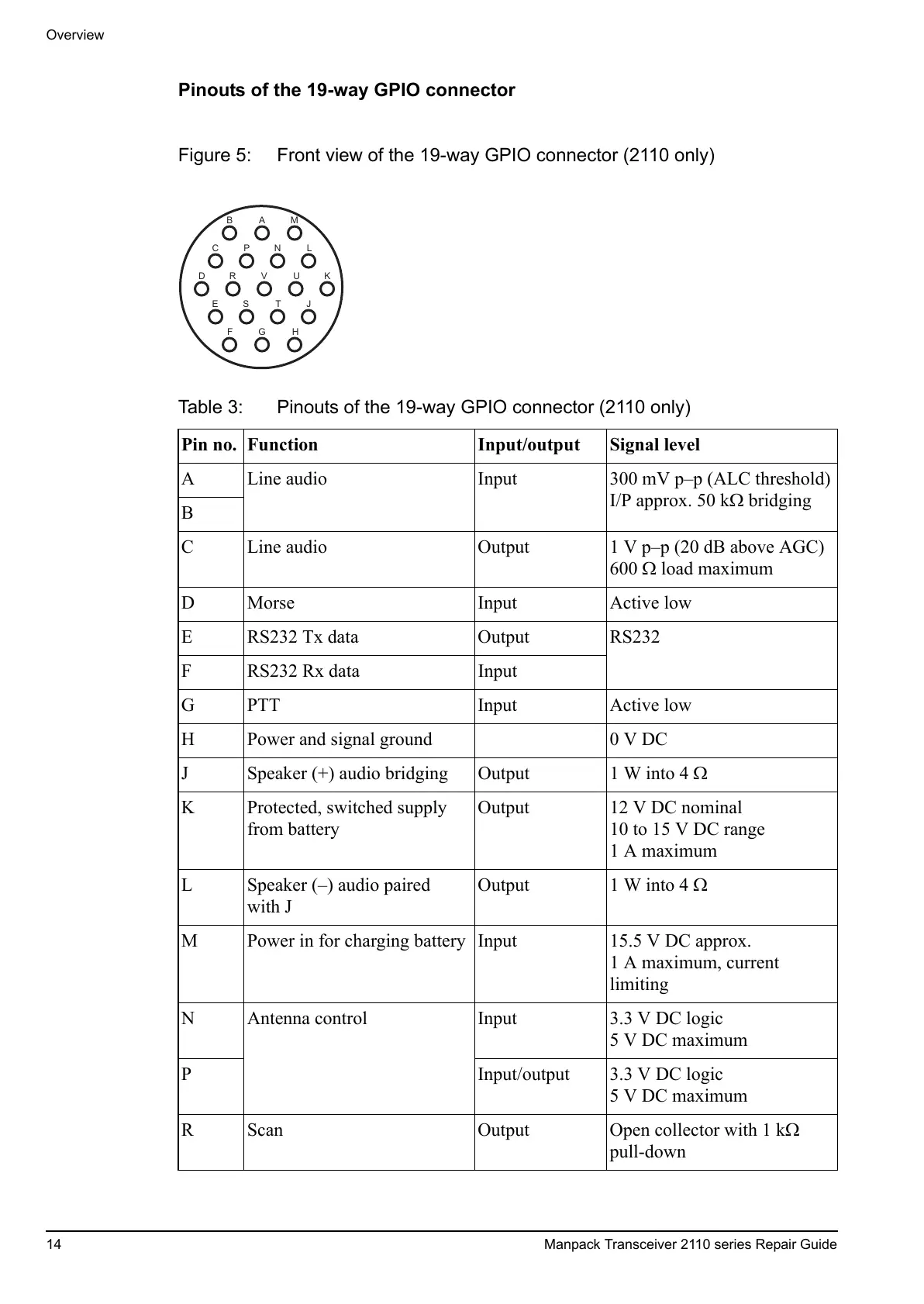
Figure 5: Front view of the 19-way GPIO connector (2110 only)
Table 3: Pinouts of the 19-way GPIO connector (2110 only)
Pin no. Function Input/output Signal level
A Line audio Input 300 mV p–p (ALC threshold)
I/P approx. 50 k bridging
B
C Line audio Output 1 V p–p (20 dB above AGC)
600 load maximum
D Morse Input Active low
E RS232 Tx data Output RS232
F RS232 Rx data Input
G PTT Input Active low
H Power and signal ground 0 V DC
J Speaker (+) audio bridging Output 1 W into 4
K Protected, switched supply
from battery
Output 12 V DC nominal
10 to 15 V DC range
1 A maximum
L Speaker (–) audio paired
with J
Output 1 W into 4
M Power in for charging battery Input 15.5 V DC approx.
1 A maximum, current
limiting
N Antenna control Input 3.3 V DC logic
5 V DC maximum
P Input/output 3.3 V DC logic
5 V DC maximum
R Scan Output Open collector with 1 k
pull-down
 Loading...


