Functional description of PCBs
Manpack Transceiver 2110 series Repair Guide 45
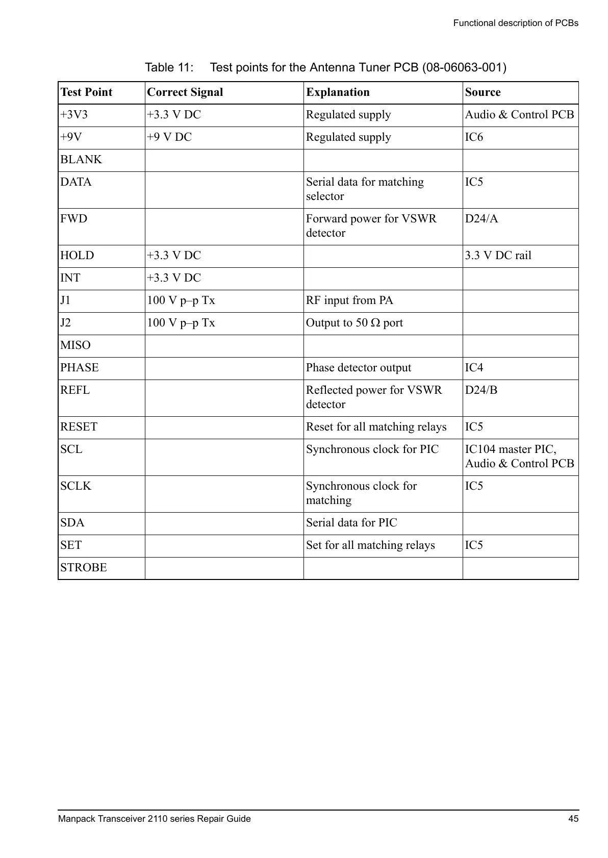
Table 11: Test points for the Antenna Tuner PCB (08-06063-001)
Test Point Correct Signal Explanation Source
+3V3 +3.3 V DC Regulated supply Audio & Control PCB
+9V +9 V DC Regulated supply IC6
BLANK
DATA Serial data for matching
selector
IC5
FWD Forward power for VSWR
detector
D24/A
HOLD +3.3 V DC 3.3 V DC rail
INT +3.3 V DC
J1 100 V p–p Tx RF input from PA
J2 100 V p–p Tx Output to 50 port
MISO
PHASE Phase detector output IC4
REFL Reflected power for VSWR
detector
D24/B
RESET Reset for all matching relays IC5
SCL Synchronous clock for PIC IC104 master PIC,
Audio & Control PCB
SCLK Synchronous clock for
matching
IC5
SDA Serial data for PIC
SET Set for all matching relays IC5
STROBE
 Loading...


