EasyManuals Logo

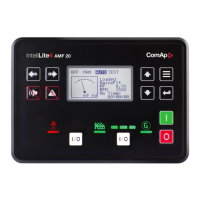
ComAp InteliLite AMF25 User Manual

ComAp InteliLite AMF25
735 pages
To Next Page IconTo Next Page
To Previous Page IconTo Previous Page
Page #43 background imageLoading...
Page #43 background image
InteliLite Global Guide
43
0 - 30 V
V 0 2 4 6 8 10 12 14
Ω 94 105 118 131 147 163 182 202
V 16 18 20 22 24 26 28 30
Ω 226 252 282 317 358 405 463 533
0 - 70 V
V 0 2 4 6 8 10 12 14 16 18 20 22
Ω 97 102 108 114 120 126 133 140 147 154 162 170
V 24 26 28 30 32 34 36 38 40 42 44 46
Ω 179 188 198 208 219 231 243 256 269 284 300 316
V 48 50 52 54 56 58 60 62 64 66 68 70
Ω 334 354 375 398 422 449 479 511 547 587 631 681
Note: This is a conversion of voltage from voltage sensor to appropriate resistance value. Use resistance
values in InteliConfig to create your specific curve. These values should be used in "Ohm" column.
Current sensors
Sensors output
range (mA)
R (Ω)
0-20 100
Image 4.22 Wiring of analog input with current sensor

Table of Contents

Questions and Answers:

Question and Answer IconNeed help?

Do you have a question about the ComAp InteliLite AMF25 and is the answer not in the manual?

ComAp InteliLite AMF25 Specifications

General IconGeneral
Inputs8 binary inputs
Outputs8 binary outputs
Power Supply8-36 V DC
CommunicationRS232, RS485
Operating Temperature-20°C to +70°C
Supported GeneratorsDiesel, gas
Controller TypeAutomatic Mains Failure Controller
ProtectionIP65

Related product manuals