CAUTION!
Switchboard lightning strikes protection according standard regulation is expected!!!
The maximum allowable current through the controller negative terminal is 3 to 8A (depends
on the
controller type and binary output load).
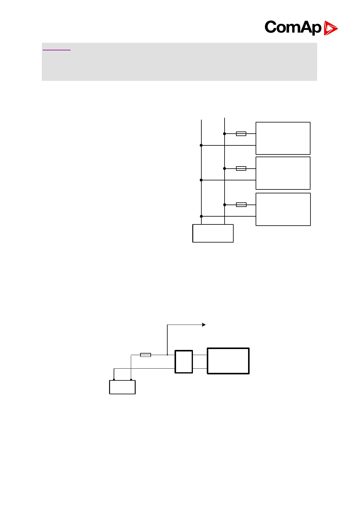
8.4. Power supply fusing
Always use according fuse (1Amp or 2Amps)
when connection controller, extension modules or
relays to a power source.
See the diagram for proper fusing.
For more extension units use separate fusing according to the table above.
Controller power supply should never be connected to starter terminals.
For the connections with 12VDC power supply an I-LBA module can be connected to controller
power terminals in order to allow the controller to continue operation during cranking if the
battery voltage dip occurs. In this case, it is not recommended to use +PWR BOUT outputs on
the controller as a source for relays, as their consumption would exhaust I-LBA capacitors very
fast.