IGS-NT Installation Guide
9.9. Binary Input wiring
Use min. 1 mm
2
cables for wiring of binary inputs.
NOTE:
The name and function or alarm type for each binary input
have to be assigned during the configuration. Binary inputs
may be used in built-in PLC as well. Please refer to the
manual of GenConfig for more information.
It is recommended to use separation diodes when multiple
binary input terminals are connected together to prevent
unwanted activation of binary input when one of the controllers
is switched off.
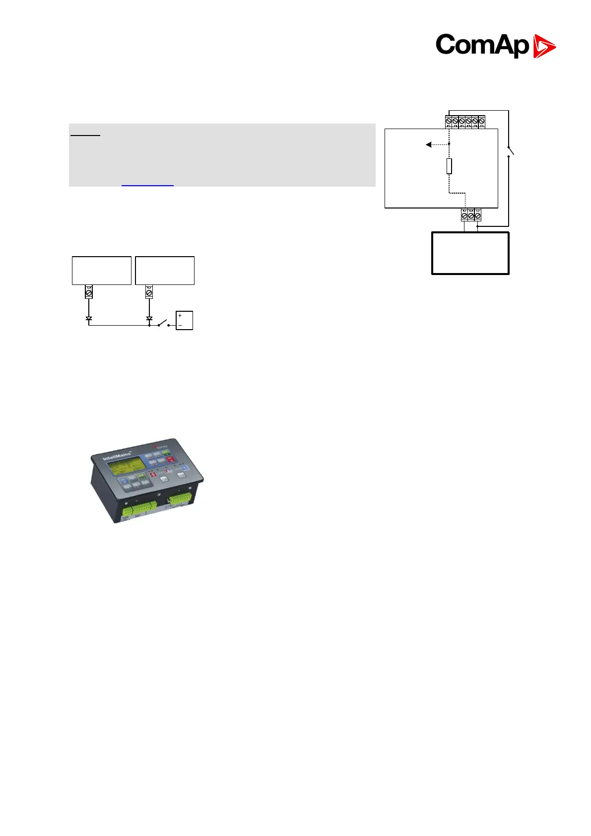
9.10. Binary Output wiring
9.10.1. Controllers without High-Side Low-Side Switch
This portion of Instalation instructions is dedicated to
controllers without High-Side Low-Side Switch. These
controllers include: IG-NT (and variations), IG-NTC (and
variations), IS-NT-BB, IM-NT
Correct wiring for Binary output is shown in the diagram below. On the left +PWR BOUT is
not used, on the right +PWR BOUT is used. If Binary outputs are connected directly to the
power source, additional fuse should be used.
Battery 24V
DC
+ -
Controller
Internal
4k7
To microprocessor