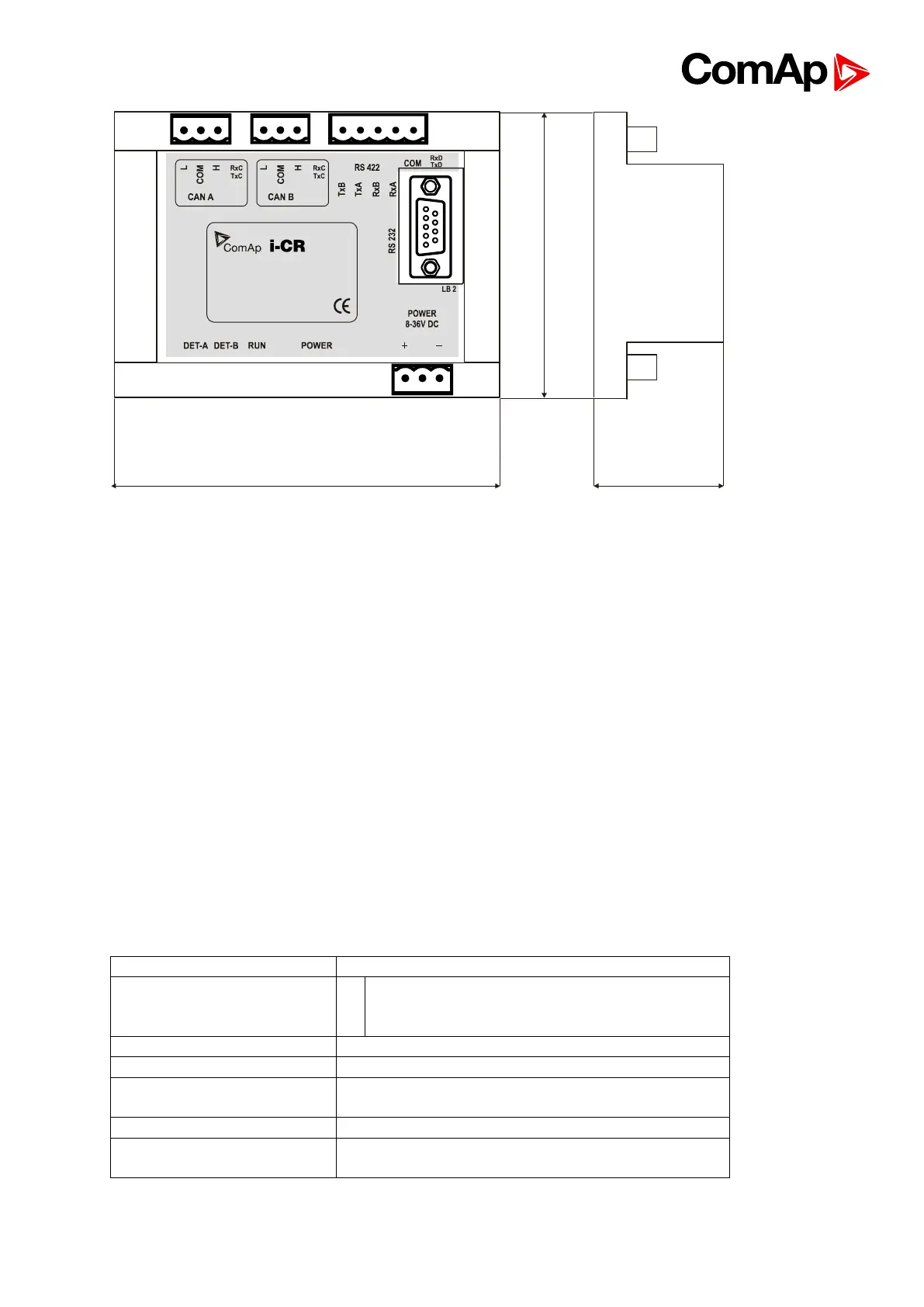
I-CR can be mounted on DIN rail (35 mm).
5.3.14. I-AOUT8
5.3.14.1. General Description
I-AOUT8 is an extension unit with 8 analog outputs. Each analog output can be switched by
jumper for.
• 0 to 20 mA
• 0 to 10 VDC
• PWM (Pulse With Modulation on 1,2 kHz)
I-AOUT8 module is connected on IGS-NT or IM-NT CAN1 (peripheral) bus. The
corresponding module Address 1 to 4 (default 1) must be set on module (by Adr.1 and Adr.2
jumpers) and in controller configuration. Communication fail is indicated in controller Alarm
list and by binary output. Use GenConfig PC tool for controller configuration.
It is possible to connect up to four I-AOUT8 units to one controller.
I-AOUT8 unit can be mounted on DIN rail (35 mm).
CAN1 terminating 120 ohm resistor jumper is connected in default. AGND terminals are on
the same potential.
0 to 10VDC ± 1% , max 5 mA
0 to 20 mA ± 1% , max 500 ohms
pwm 1200 Hz, 5V level, max 10 mA
CAN1, with jumper selectable address 1 to 4
Jumper selectable terminating resistor 120 ohms.