Powering supply from the mains: features and connection
37
HS-RC-C5E-TIN_03.fm
00/0211
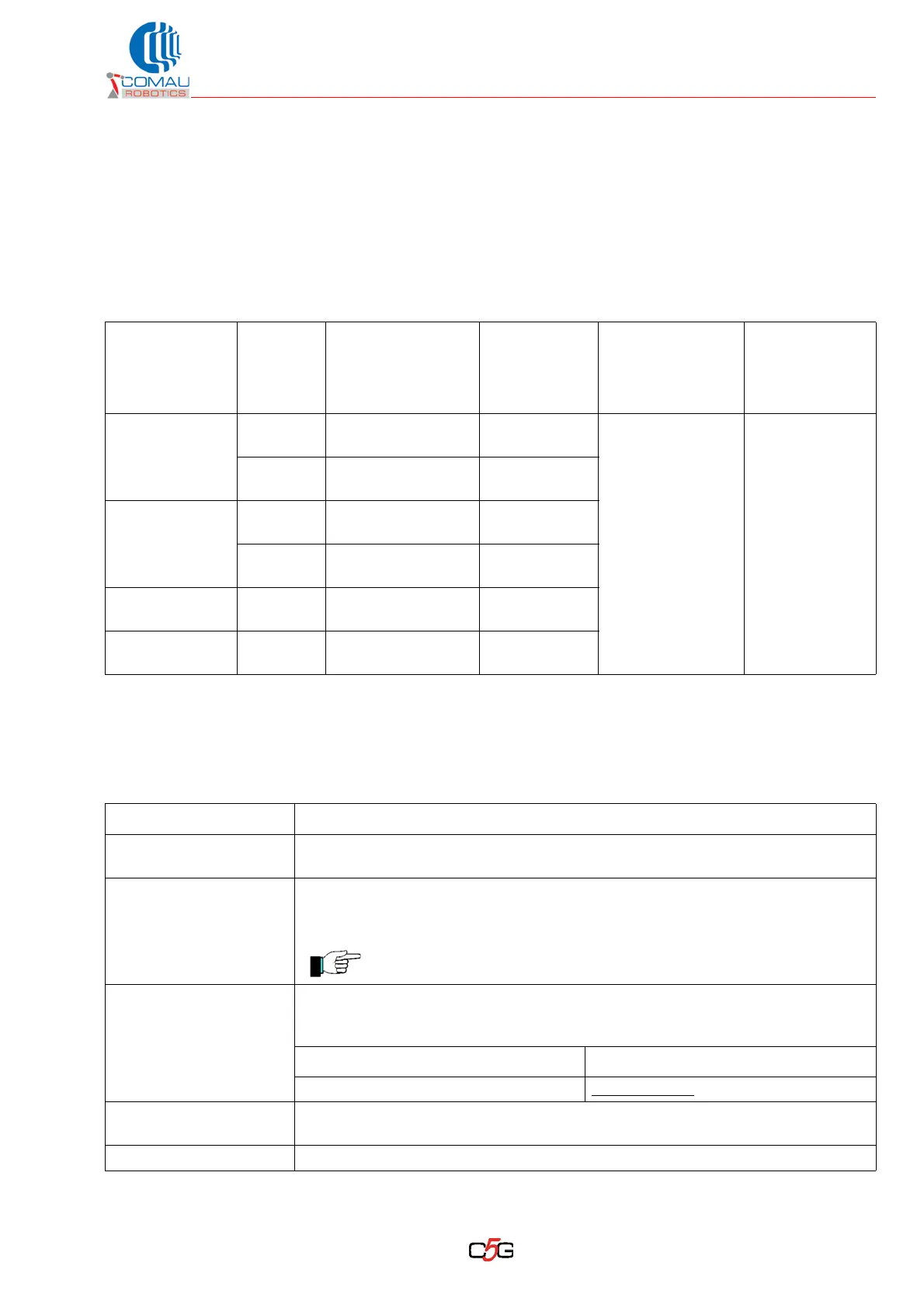
4.3 Power supply features
Before connecting the power supply, read carefully the following information:
– Technical features
– Technical details
– Earth connection diagram.
*¹ with version supplied with transformer and voltage switching on terminal board
*² for length up to 20 m / 66 ft
*³ by the connection point is installed an automatic magneto-thermal switch,
Tab. 4.1 - Technical features
C5G Control
Unit
Installed
Power
Powering and
earth wires
minimum section
*²
gG Fuse
up the C5G
Required supply
voltage
C5G main
circuit breaker
power interrupt
C5G-ACC1
3 kVA
2,5 mm²
(14 AWG)
10 A
50 a 60 Hz (±2 Hz)
400 Vac -10%
a 500 Vac +10%
optional *¹
400 Vac -10%
a 575 Vac +10%
6 kA a
500 Vac
12 kVA
6 mm²
(10 AWG)
25 A
C5G-ACC3
8 kVA
6 mm²
(10 AWG)
25 A
12 kVA
6 mm²
(10 AWG)
25 A
C5G-ACC3P 12 kVA
6 mm²
(10 AWG)
25 A
C5G-ACC5 12 kVA
6 mm²
(10 AWG)
25 A
Tab. 4.2 - Technical details
Component / function Description
Fuse up the C5G
The fuse shall be gG type, with features similar to the ones of the Siemens
3NAx-xxx series
Differential switch up the
C5G
When a differential switch type B is requested (AC/DC sensitive according to
norm IEC 60755), use a model featuring a fault current value >= 300 mA and
adjustable triggering time > 100 ms.
No automatic circuit breakers (fault current = 30 mA) are allowed.
Powering cable
Depending on the Customer supply specifications an armored quadripole (three
phases plus earth) cable in compliance with norm IEC 60332-1 or CEI 20/35 is
requested to carry out the connection to the mains.
On Main Circuit breaker On X120 connector
Max cable size: 10 mm² / 8 AWG Max cable size
: 6 mm² / 10 AWG
Cable gland by cabinet
base
The M25 type cable gland supplied is suitable for a cable featuring an outside
diameter between 13 and 18 mm (between 0.5 and 0.71 in)
Additional recommend. Protect the cable using suitable casing (norm IEC 60204-1).