Safety circuits: minimum requirements for integration
58
HS-RC-C5E-TIN_05.fm
00/1010
6.7 Safe cut-off for 24 Vdc power supply: using
the internal or external power supplies
6.7.1 Solution with power supply taken from the X106/SDM
The solution described herein feature the following structure:
– the 24 Vdc power supply is delivered by the internal power supply AMS-ASM32 or
taken from outside source through the X30
– the 24 Vdc power supply for the I/O user’s modules (direct and cut power supply)
can be taken from the X106/SDM connector, at the disposal of the user.
For further information, refer to the Overview for 24 Vdc power supply in the
Control Unit (see par. 6.1 on page 115).
Preliminary procedures / notes
The electric wiring diagram described below are to be used only to
understand the connections. The integrator shall analyse the safety
requirements of the cell/line and carry out the connections according
to the needs.
Status: – Electric energy off
Material: – C5G-UCK: user connector kit, for
SDM module
Equipment: – Screwdriver set
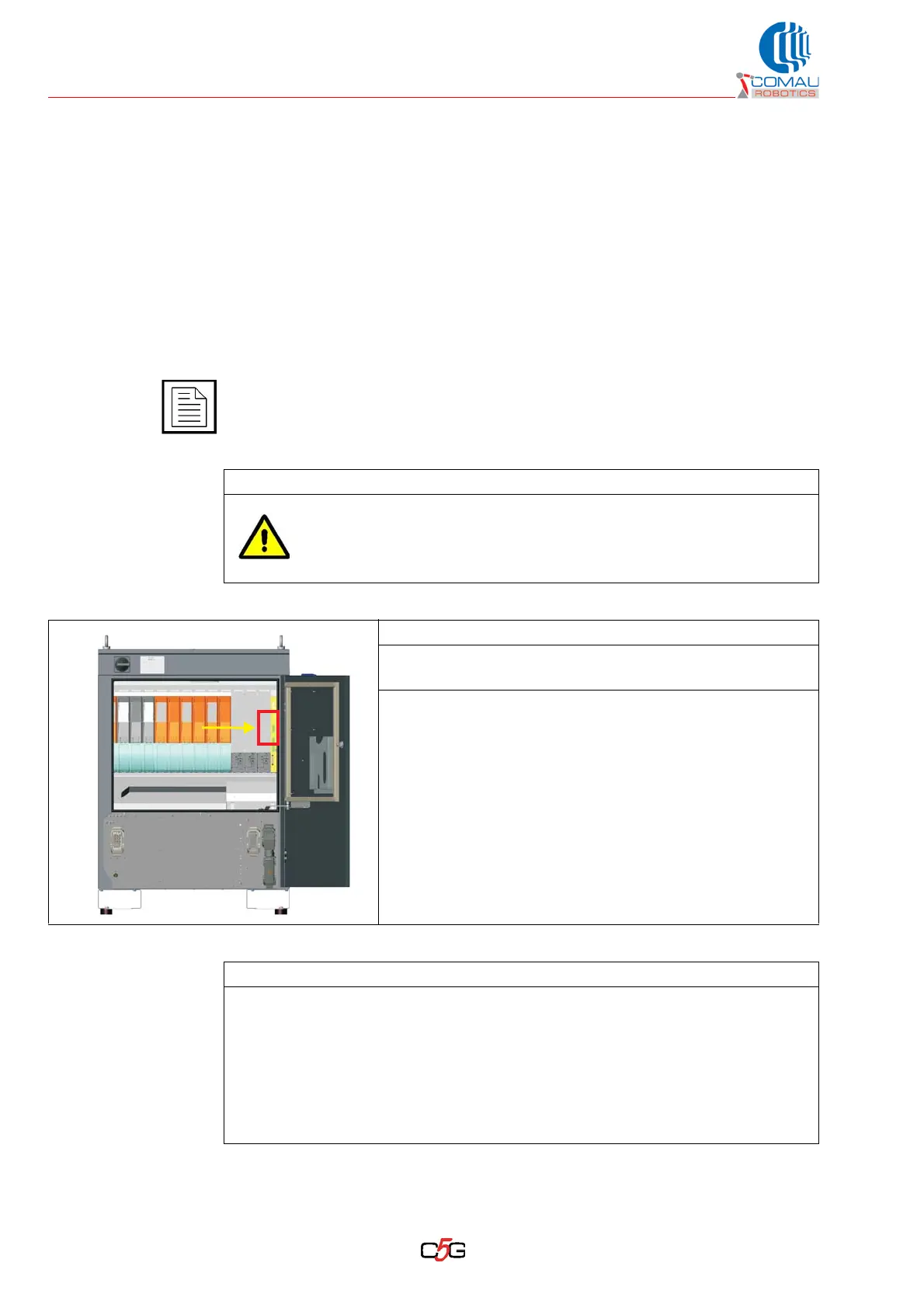
Operating procedure
a. Carry out the circuit as shown in the outline wiring diagram in Fig. 6.4 - 24 Vdc
power supply cutoff circuit on X106/SDM: outline diagram on page 59.
b. If necessary, depending on the user choice for the circuitry, deliver the 24 Vdc
power supply through the X30 connector. In that case the JP200 position shall be
adjusted (refer to par. 7.3 Selecting the 24 Vdc power supply source on page 62).
c. Power the I/O modules taking the power supplies on the X106/SDM connector.