Safety circuits: minimum requirements for integration
50
HS-RC-C5E-TIN_05.fm
00/1010
6.6 E-Stop circuits: inputs and control procedure
for stop circuits and mushroom-shaped push
button on Teach Pendant
– How to wire the X30 connector
– Further details about the stop circuit signals
– X30/CIP connector: pins
– Safety signals: reference wiring diagram
– Troubleshooting for safety signals coming from unsuitably installed safety devices.
6.6.1 How to wire the X30 connector
Status: – Power off
Material: – Harting male contacts
no. 32 pins 09.15.000.6103 (0.5 mm² /
20 AWG),
no. 9 pins 09.15.000.6101 (1.5 mm² /
16 AWG),
no. 1 pin 09.15.000.6106 (2.5 mm² /
14 AWG)
connector and cap (supplied together
with the Control Unit)
Equipment: – Clip for Harting contacts, code
09.99.000.0001
– Puller for Harting contacts, code
09.99.000.0012
Preliminary procedures / notes
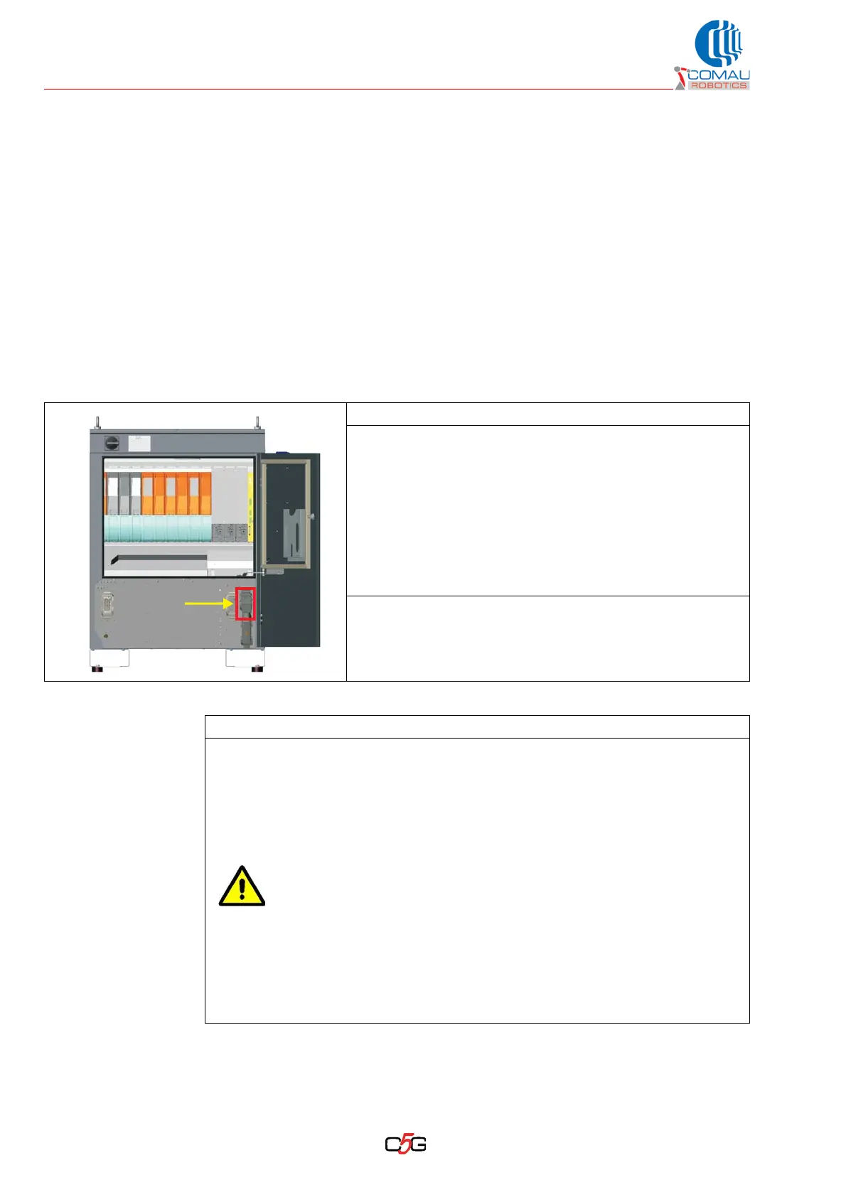
– The input/output signals for the stop circuits are available on the X30/CIP
connector located by the Control Unit base (details about the pins in Fig. 6.1
- X30/CIP connector: pinouts on page 54).
– Depending on the used wire section/current required, use the 0.5 mm², 1.5 or 2.5
mm² male pin for the powering lines, signals and/or jumpers.
The emergency stop push button on the Teach Pendant is not
controlled by the stop circuit inside the C5G.
The integrator shall connect the above mentioned contacts to the
machine emergency stop circuit by means of the connection
available on the X30 connector.
Failing to perform the connection will highly endanger the
programming as well as the machine operators.