Safety circuits: minimum requirements for integration
49
HS-RC-C5E-TIN_05.fm
00/1010
*¹ Value specified by manufacturer.
Operating procedure
If the time has to be adjusted:
a. Disconnect the power from the
mains.
b. Determine the time required
according to the data in
Tab. 6.1.
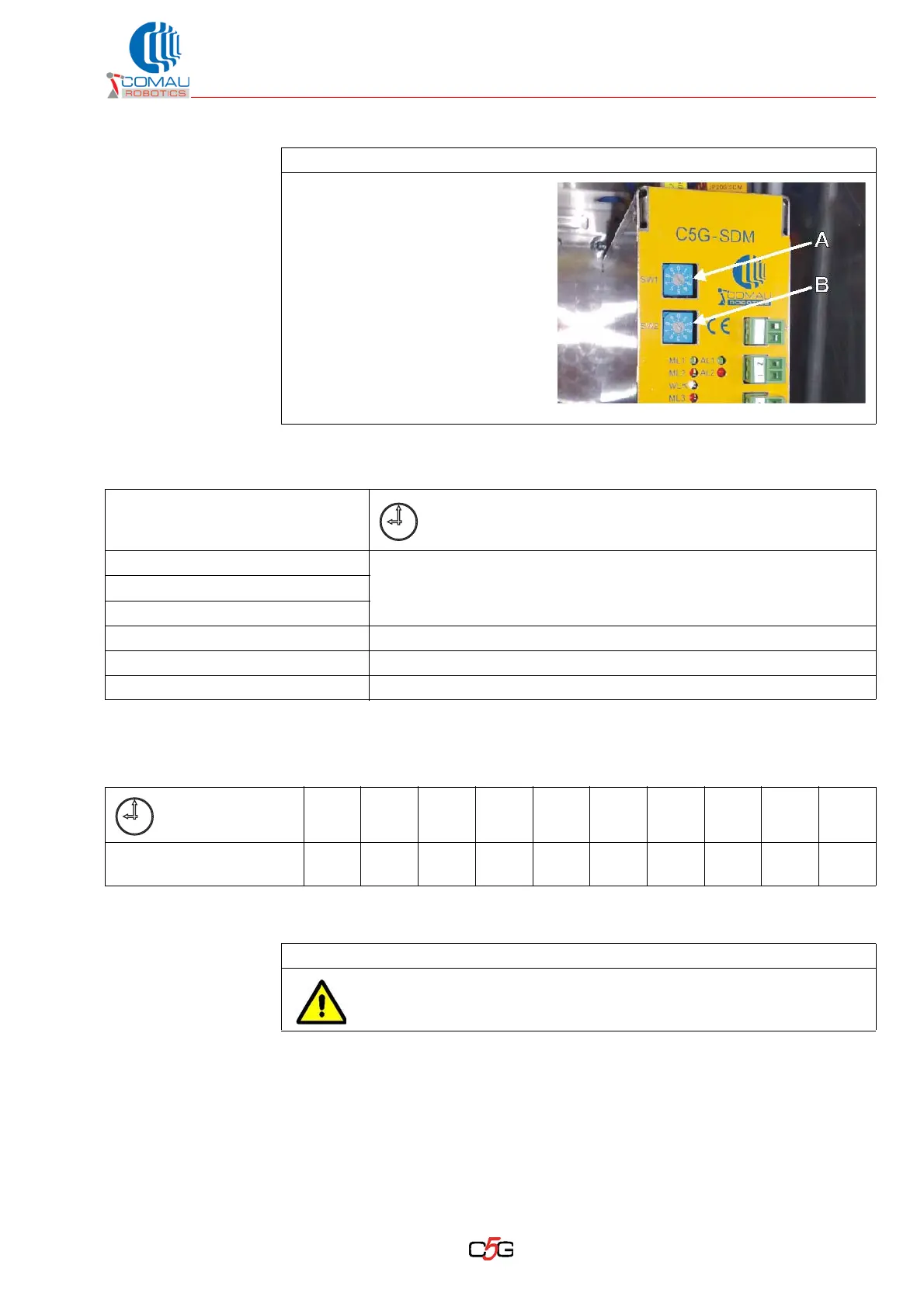
c. Check or possibly set both
rotating selector switches SW1
(A) and SW2 (B) on module
SDM according to Tab. 6.2.
Tab. 6.1 - Time to be set depending on Robot models
Robot models
Time to be set for SDM module
(preferential according to Robot model and typical applications)
SMART 5 Six / NS
1.5 seconds *¹SMART 5 NM
SMART 5 NJ
Square YZ-500 2 seconds
SMART NX1-600 2 seconds
SMART NX1-800 6 seconds
Tab. 6.2 - Time and position for the rotating selector switches on
SDM module
Time (seconds)
0 0,5 1 1,5 *¹ 2 2,5 3 4 5 6
Selector position
SW1 / SW2
0123 *¹456789
Follow-up procedure
Do not turn on the main switch to power the Control Unit until the
installation procedure is completed.