EasyManuals Logo
Home>Comau Robotics>Control Unit>C5G

Comau Robotics C5G Instruction Handbook

Comau Robotics C5G
72 pages
To Next Page IconTo Next Page
To Previous Page IconTo Previous Page
Page #54 background imageLoading...
Page #54 background image
Safety circuits: minimum requirements for integration
54
HS-RC-C5E-TIN_05.fm
00/1010
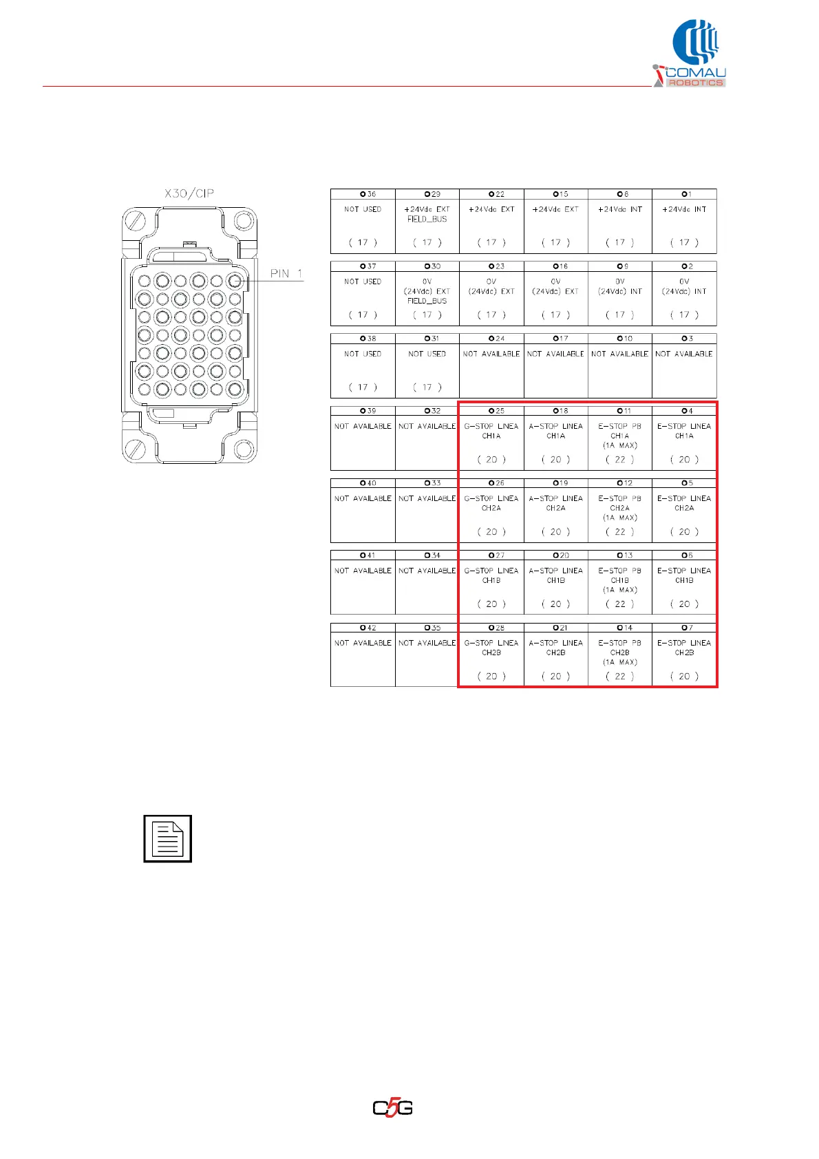
6.6.3 X30/CIP connector: pins
Fig. 6.1 - X30/CIP connector: pinouts
Legend:
Not Used / Not Available
The 0V shown are connected together. The internal power supplies (0V INT, 0V
EXT and 0V Field Bus) are connected to one another, to the 0V inside the Control
Unit and to the earth.
The internal connections related to the X30 connector are shown in the Control
Unit wiring diagram.
External View

Table of Contents

Other manuals for Comau Robotics C5G

Questions and Answers:

Question and Answer IconNeed help?

Do you have a question about the Comau Robotics C5G and is the answer not in the manual?

Comau Robotics C5G Specifications

General IconGeneral
BrandComau Robotics
ModelC5G
CategoryControl Unit
LanguageEnglish