Safety circuits: minimum requirements for integration
53
HS-RC-C5E-TIN_05.fm
00/1010
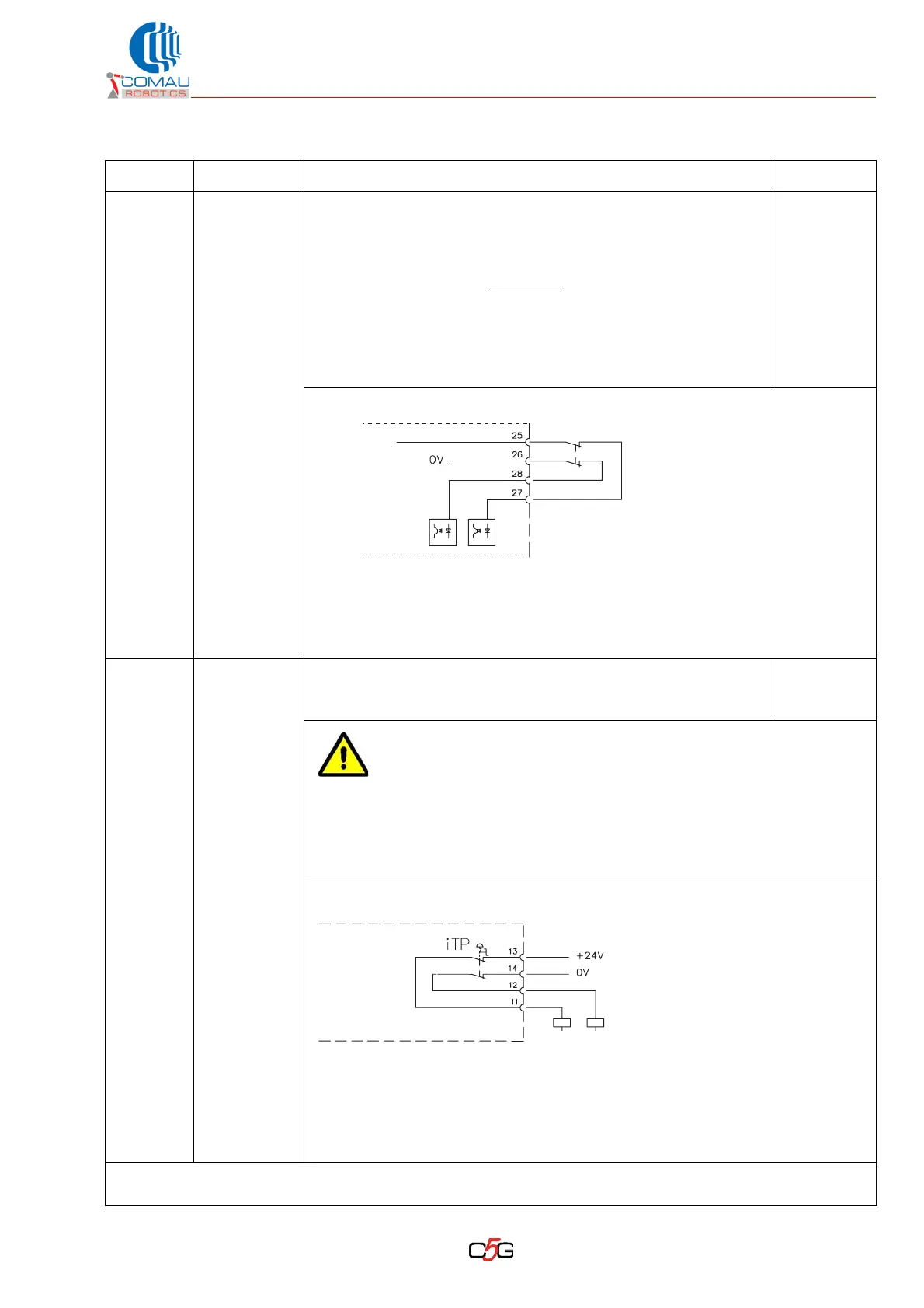
Input
Gen-Stop
Line
25, 27
26, 28
Status:it is always enabled and triggers the stopping mode (norm
EN60204-1) depending on the selected operating mode:
• category 1 in automatic mode
• category 0 in programming mode *¹
Signal: input used for the safety stop
function; connect a pair of
not-energized contacts of a safety device coming from the line. It is
physically identical to the E-Stop input and can be used for
functional purposes to trigger the Robot emergency stop without
acting on the E-Stop, that is typically enabled for wider geographic
areas.
$SDI[43]
Channel 1
$SDI[44]
Channel 2
Electric features:
– self-restoring fuse 1 A
– current on the contacts between 20 and 50 mA per each input
– voltage 24 Vdc
Output
E-Stop PB
11, 13
12, 14
Status: it is always enabled.
Signal: output for the (not-energized) contacts of the emergency
stop push button on the Teach Pendant.
$SDI[120]
Both
channels
The emergency push button on the Teach Pendant is not directly
connected to the Control Unit emergency stop circuit.
The integrator shall:
–properly interlock the push button contacts with the machine
(cell / plant) emergency stop circuit
– remember to include also the Teach Pendant E-Stop push button in the
procedure for the periodic inspection of the machine emergency
devices.
Inside contacts electric features:
– max current 1 A
– typ voltage 24 Vdc, max 50 V
Note: install quick-fit protection fuse 1 A on the 24 Vdc power supply input (to be
carried out by the integrator)
*¹ For safety reasons, in Programming mode only category 0 stops are enabled (in compliance with EN
60204-1).
Tab. 6.3 - X30/CIP connector: safety signal definition (Continued)
Signal Pin on X30 Definition and purpose Diagnosis
X30
C5G
General
Stop
+24V Int
Internal
E-Stop
X30
C5G
iTP = Teach Pendant E-Stop