Start up
69
HS-RC-C5E-TIN_07.fm
00/0310
8.3 Errors caused by incorrect connections in
the safety circuits or in the ystem inputs
To start properly, the Control Unit requires some safety circuits and system diagnostic
inputs to be closed again.
Find below the minimum requirements to be complied with.
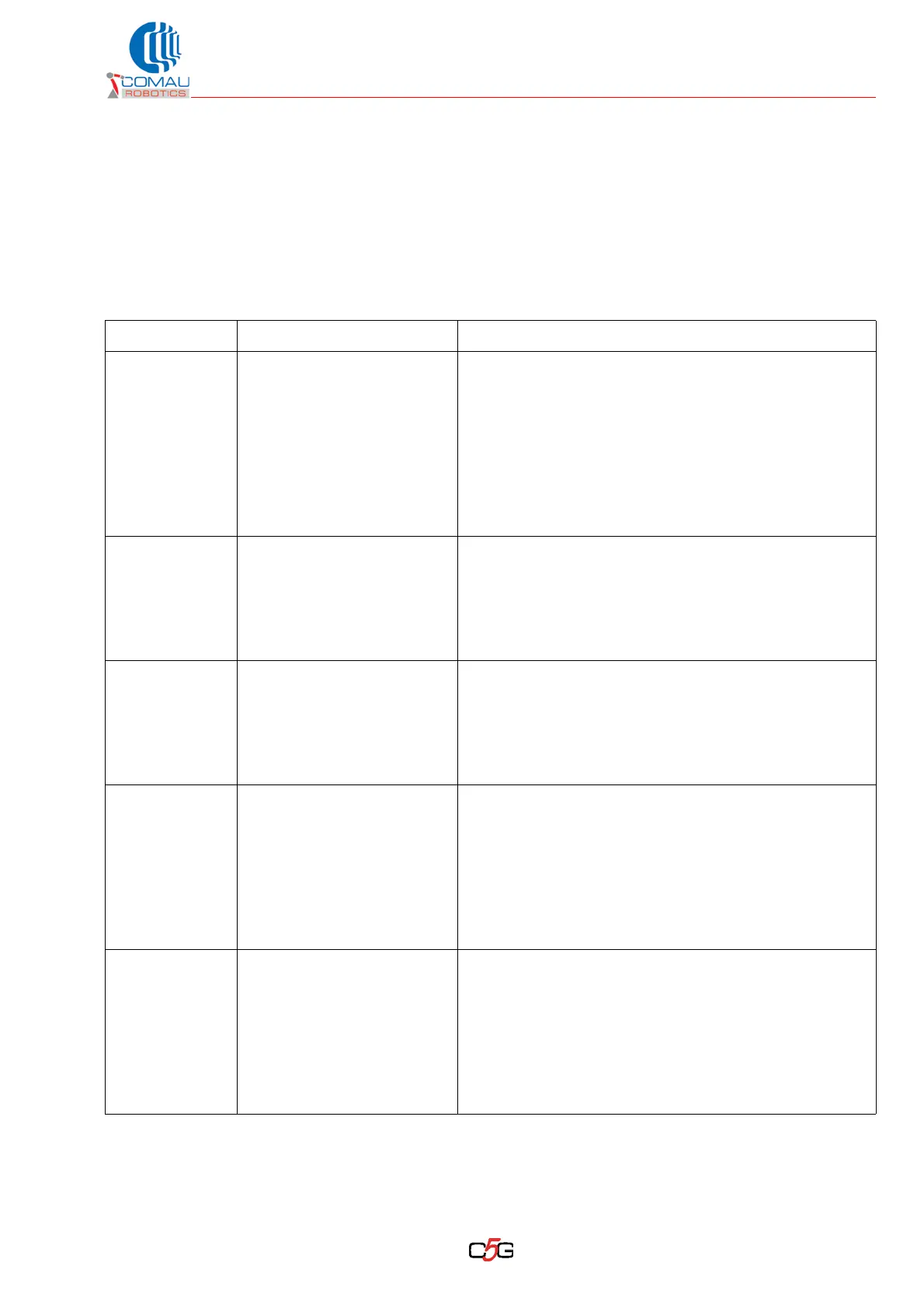
Tab. 8.1 - Circuits and signals to start the C5G
Circuit Description Minimum requirements / Notes
E-Stop Emergency stop from outside
– The 2 safety channels shall be closed again
Notes:
– Signals available on X30 connector
– Refer to par. 6.6 E-Stop circuits: inputs and control
procedure for stop circuits and mushroom-shaped
push button on Teach Pendant on page 50
– Refer to par. 6.3 C5G-ISAK5: power supply kit for
applications on page 123 of Technical Specification
handbook.
Auto-Stop
(Fence)
Limit switch controlling the cell
access doors
– The 2 safety channels shall be closed again
Notes:
– Signals available on X30 connector
– Refer to par. 6.6 E-Stop circuits: inputs and control
procedure for stop circuits and mushroom-shaped
push button on Teach Pendant on page 50
General Stop Area stop
– The 2 safety channels shall be closed again
Notes:
– Signals available on X30 connector
– Refer topar. 6.6 E-Stop circuits: inputs and control
procedure for stop circuits and mushroom-shaped
push button on Teach Pendant on page 50
Robot alarm Flange alarm on Robot wrist
– The Robot Allarm input shall be closed again
Notses:
– Signals available on X2 connector of the third
AMS-IAM module (a connector serving as plug is
available to close the circuits)
– Alternatively, with C5G-SMK option installed, the
signals are available on connector by Robot border
area.
Air input Air alarm by robot border area
– Air Input input shall be closed again
Notes:
– Signals available on X2 connector of the third
AMS-IAM module (a connector serving as plug is
available to close the circuits)
– Alternatively, with C5G-SMK option installed, the
signals are available on connector by Robot border
area.

 Loading...