Safety circuits: minimum requirements for integration
55
HS-RC-C5E-TIN_05.fm
00/1010
6.6.4 Safety signals: reference wiring diagram
– Stand-alone control reference diagram
– Centralized control reference diagram
.
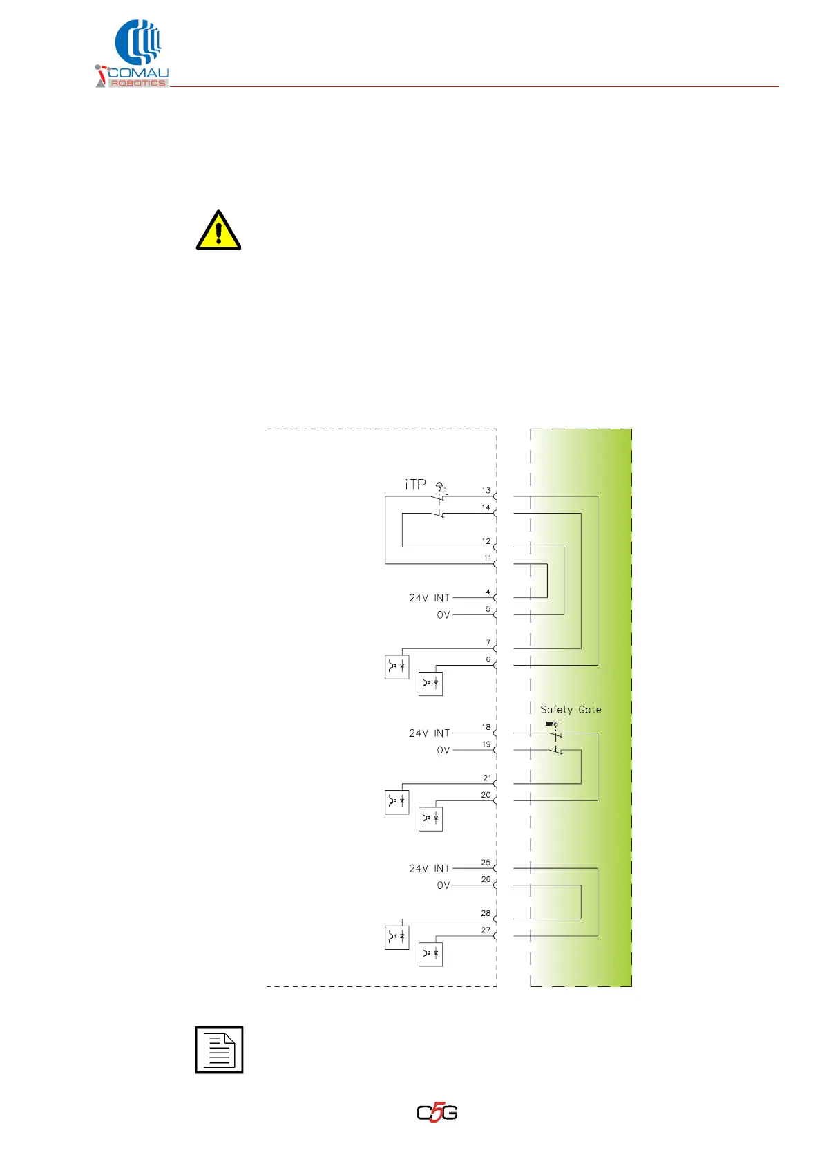
Fig. 6.2 - Stand-alone control reference diagram
The mushroom-shaped push button in the C5G shall be included in the
emergency safety circuit.
The wiring diagrams below are to be used only as guidelines to understand the
connections. The integrator shall assess the cell/line safety requirements and
carry out the connections accordingly.
The signals electric features are to be found in Tab. 6.3 - X30/CIP connector:
safety signal definition on page 52.
Internal
E-Stop
External
E-Stop
Auto-Stop
(Fence)
General
Stop
C5G
X30
Stand Alone
Operations
iTP = Teach Pendant E-Stop