Safety circuits: minimum requirements for integration
52
HS-RC-C5E-TIN_05.fm
00/1010
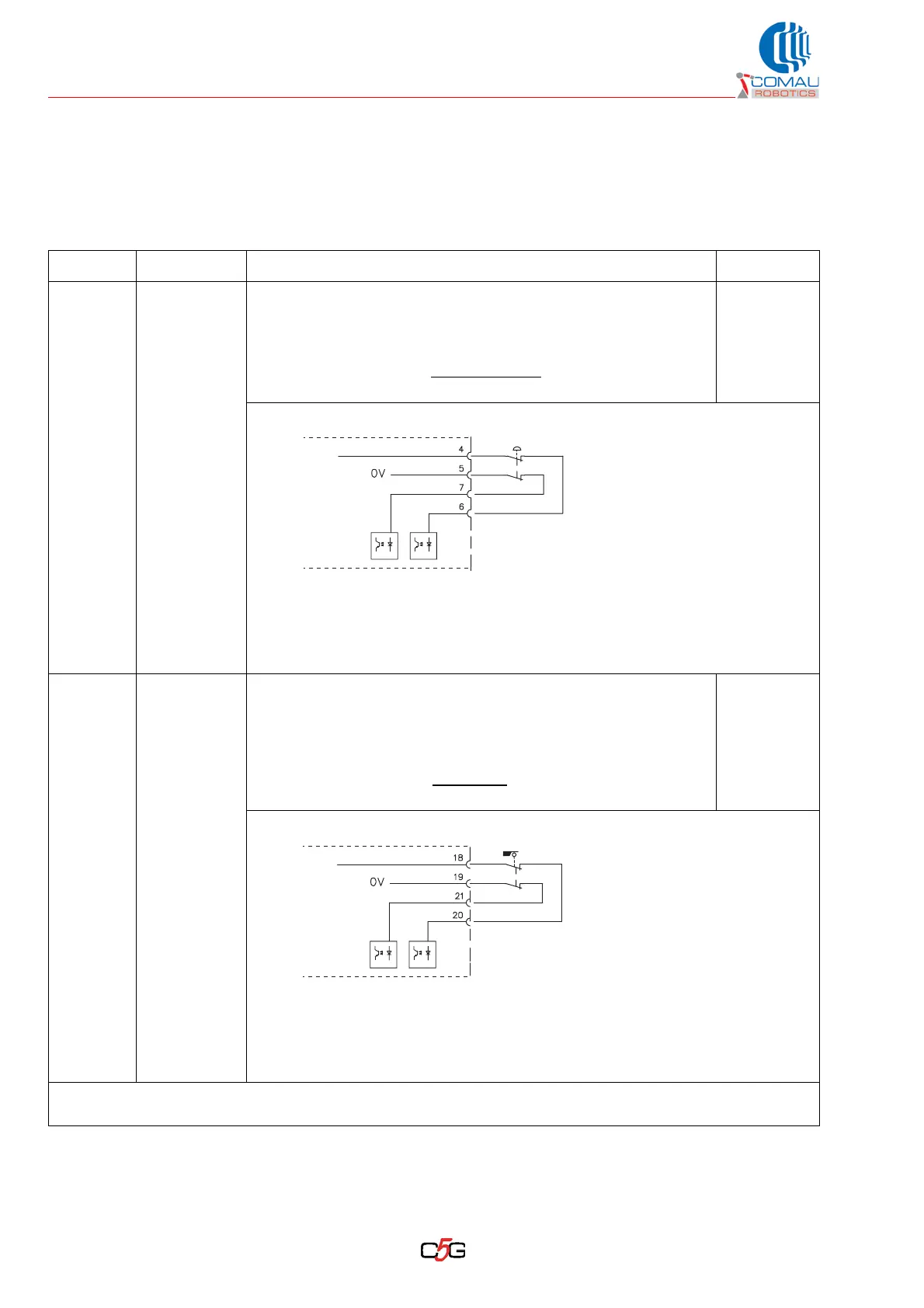
6.6.2 Further details about the stop circuit signals
The input/output signals for the stop circuits are available on the X30/CIP connector
located by the Control Unit base.
Tab. 6.3 - X30/CIP connector: safety signal definition
Signal Pin on X30 Definition and purpose Diagnosis
Input
E-Stop
Line
4, 6
5, 7
Status: it is always enabled and triggers the stopping mode (norm
EN60204-1) depending on the selected operating mode:
• category 1 in automatic mode
• category 0 in programming mode *¹
Signal: input used for the emergency stop
function; connect a pair
of not-energized contacts of a safety device coming from the line.
$SDI[41]
Channel 1
$SDI[42]
Channel 2
Electric features:
– self-restoring fuse 1 A
– current on the contacts between 20 and 50 mA per each input
– voltage 24 Vdc
Input
Auto-Stop
Line
18, 20
19, 21
Status: it is enabled in automatic operating mode only and triggers
a stop according to category 1 (norm EN60204-1). By selecting the
Programming mode, the C5G will be controlled by the Enabling
Device (on Teach Pendant) and the Auto-Stop input will be
disabled.
Signal: input used for the safety stop
function; connect a pair of
not-energized contacts of a safety device coming from the line.
$SDI[47]
Channel 1
$SDI[48]
Channel 2
Electric features:
– self-restoring fuse 1 A
– current on the contacts between 20 and 50 mA per each input
– voltage 24 Vdc
*¹ For safety reasons, in Programming mode only category 0 stops are enabled (in compliance with EN
60204-1).
X30
C5G
External
E-Stop
+24V Int
X30
C5G
Auto-Stop
(Fence)
+24V Int