Circuits for minor automation routines: minimum requirements for integration
63
HS-RC-C5E-TIN_06.fm
00/0411
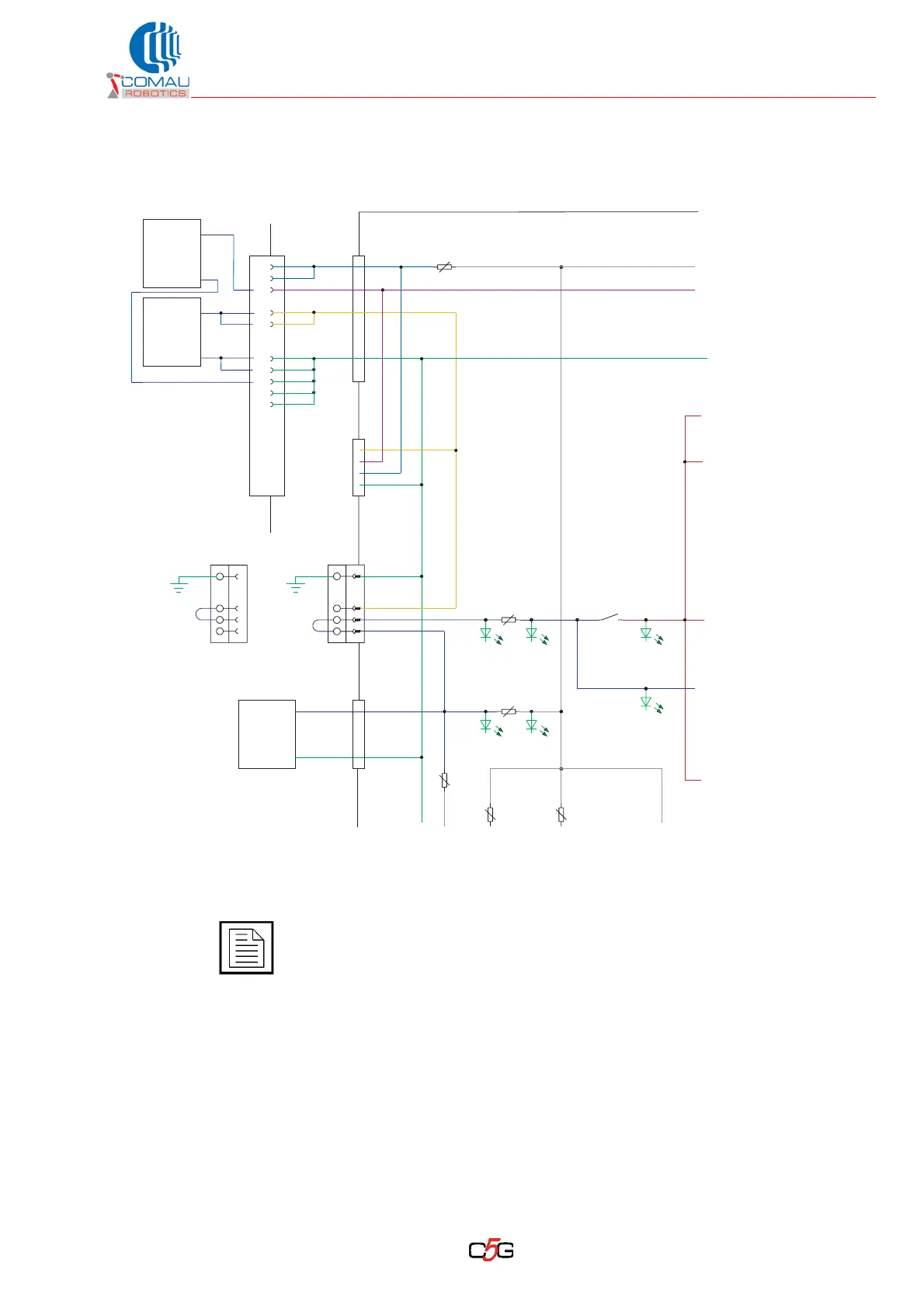
Fig. 7.1 - Circuit to select the 24 Vdc source: power supply
source selection reference diagram
Postion A: 24Vdc power internal source
Position B: 24 Vdc power external source, coming from X30
For further details about the 24 Vdc power supply source, please refer to par. 6.1
Overview for 24 Vdc power supply in the Control Unit on page 115 of the manual
“Technical specifications”.
SUPPLY
24V
0V
24V
EXT.
SUPPLY
24V
0V
24V
EXT.
AB
JP200
24V EXT.
24V INT.
ASM
AUX.
SUPPLY
MODULE
24V
0V
5A
X30
1A
X102
JP200
X100
INT./EXT.
8A
1
8
15
22
29
2
9
16
23
30
24V EXT.
24V INT.
24V EXT.
24V INTP
24V EXT.
DRIVE ON
FIELD BUS
X122
0V
5A
5A1A
SDM MODULE
SL1 P5A
SL2 P8A PSF
PIO