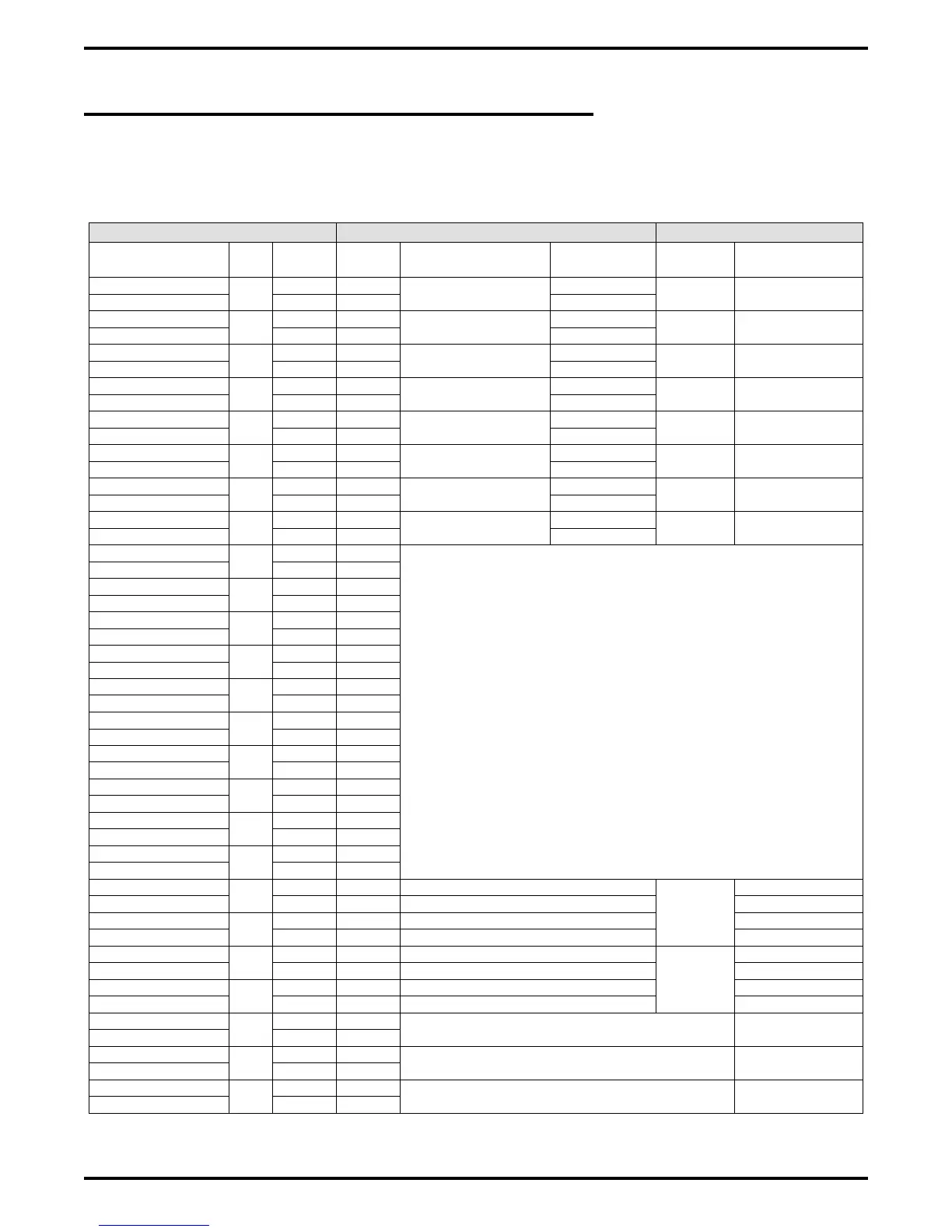
2.5.4 Connecting Stations To The G0408
This table shows the color-coded connections for a G0408 common equipment cabinet.
Table 2–3: Connecting Stations To The G0408 Common Equipment Cabinet
25-Pair Connections Two-Wire Connections Station Connections
Wire Color Pair Pin No.
Clip
Term.
Pair Wire Color Station Location
White-Blue
1
26 1
Signal Path
Green
10
Blue-White 1 2 Red
White-Orange
2
27 3
Signal Path
Green
11
Orange-White 2 4 Red
White-Green
3
28 5
Signal Path
Green
12
Green-White 3 6 Red
White-Brown
4
29 7
Signal Path
Green
13
Brown-White 4 8 Red
White-Slate
5
30 9
Signal Path
Green
14
Slate-White 5 10 Red
Red-Blue
6
31 11
Signal Path
Green
15
Blue-Red 6 12 Red
Red-Orange
7
32 13
Signal Path
Green
16
Orange-Red 7 14 Red
Red-Green
8
33 15
Signal Path
Green
17
Green-Red 8 16 Red
Red-Brown
9
34 17
Spare Pairs
Brown-Red 9 18
Red-Slate
10
35 19
Slate-Red 10 20
Black-Blue
11
36 21
Blue-Black 11 22
Black-Orange
12
37 23
Orange-Black 12 24
Black-Green
13
38 25
Green-Black 13 26
Black-Brown
14
39 27
Brown-Black 14 28
Black-Slate
15
40 29
Slate-Black 15 30
Yellow-Blue
16
41 31
Blue-Yellow 16 32
Yellow-Orange
17
42 33
Orange-Yellow 17 34
Yellow-Green
18
43 35
Green-Yellow 18 36
Yellow-Brown
19
44 37
RS232
Data Port
A
TD
Brown-Yellow 19 38 RD
Yellow-Slate
20
45 39 CTS
Slate-Yellow 20 40 SG
Violet-Blue
21
46 41
RS232
Data Port
B
TD
Blue-Violet 21 42 RD
Violet-Orange
22
47 43 CTS
Orange-Violet 22 44 SG
Violet-Green
23
48 45
Common Audible
Green-Violet 23 46
Violet-Brown
24
49 47
Station 17 Audible
Brown-Violet 24 48
Violet-Slate
25
50 49
Power Fail Station
Slate-Violet 25 50
IMI66–107 Digital Telephone System
Installing The DSU 2 – 19