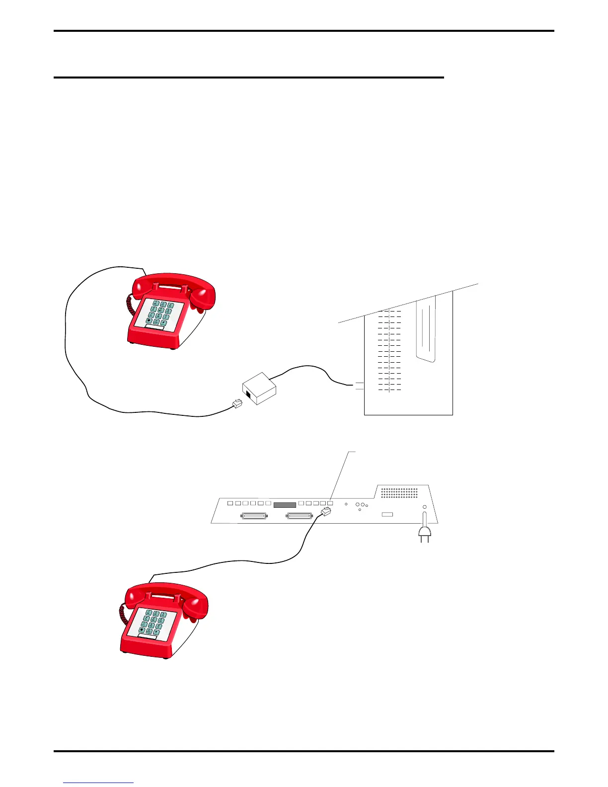
2.7 Connecting A Power Failure Station
The system provides a tip and ring pair connected to line 1 as an emergency power failure
circuit. This circuit is active during a commercial AC power failure if an external battery
assembly is not installed to provide battery back-up power to the system. Connect an industry
standard, single-line telephone, such as a model 2500, to a power failure pair and use it to
provide communications capability until the AC power to the system is restored.
NOTE: The system also provides one power failure connection with each add-on expansion
module.
Figure 2–11: Making A Power Failure Connection
37
38
39
40
41
42
43
44
45
46
47
48
49
50
{
Power Failure Jack
(16-Line, 32-Station Base Unit)
Power Failure Terminals on
Station Connection Block
(4-Line, 8-Station and 8-Line, 16-Station Base Units)
CAJS085
Typical Industry Standard
Non-electronic Telephone
(Power Failure Interface)
Typical Industry Standard
Non-electronic Telephone
(Power Failure Interface)
Digital Telephone System IMI66–107
2 – 28 Installing The DSU