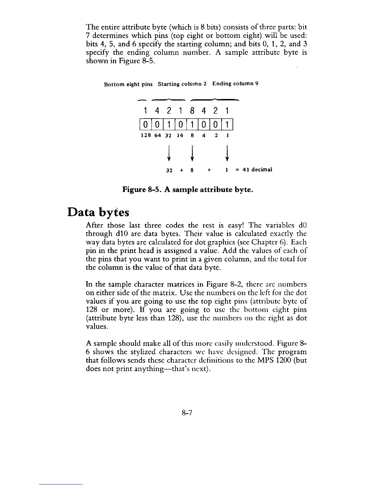
The
entire attribute
byte
(which
is
8 bits) consists
of
three parts: bit
7 determines
which
pins (top eight
or
bottom
eight) will be used:
bits
4,
5, and 6 specify the starting
column;
and
bits
0,
1,
2,
and
3
specify the ending
column
number.
A sample attribute
byte
is
shown
in Figure 8-5.
Bottom
eight
pins
Starting
column
2
Ending
column
9
142
1
842
1
10101110111010111
128
64
32
16
8 4 2
32
+ 8
+
I
=
41
decimal
Figure
8-5. A
sample
attribute
byte.
Data
bytes
After those last three codes the rest is easy!
The
variables
dO
through
dIO are data bytes.
Their
value is calculated exactly the
way
data bytes are calculated for
dot
graphics (see
Chapter
6). Each
pin
in
the
print
head is assigned a value.
Add
the values
of
each
of
the pins that
you
want
to
print
in a given
column,
and the total for
the
column
is the value
of
that
data byte.
In the sample character matrices in Figure
8-2, there are
numbers
on
either side
of
the
matrix.
Use
the
numbers
on
the left for the
dot
values
if
you
are
going
to use the
top
eight pins (attribute byte
of
128
or
more).
If
you
are going to use the
bott0111
eight pins
(attribute
byte
less than 128), use the
numbers
on
the right
as
dot
values.
A sample should
make
all
of
this
more
easily understood. Figure 8-
6
shows
the stylized characters
we
have designed.
The
program
that
follows sends these character definitions to the
MPS
1200 (but
does
not
print
anything-that's
next).
8-7